37 this diagram features a
Diagram Maker | Online Diagramming and Design Solution Diagram layouts auto-adjust as you keep adding new shapes. Unique features like Tidy snap objects back into place, keeping your diagram organized. Use illustrations, icons and photos: Many diagramming solutions are stuck in the 70s. Venngage lets you access 40K+ icons and illustrations, and free stock photo libraries to bring your diagrams to life. Feature Diagram - an overview | ScienceDirect Topics A feature diagram is a tree with the root representing a concept (e.g., a cyber-physical system) and its descendant nodes representing the concept features. Relationships between a parent feature and its child features (or sub-features) can be categorised as follows: •. Mandatory—the child feature is required. •.
Class Diagram | Types & Examples | Relationship and Advantages Class Diagram provides a static view of the application, and its mapping ability with object-oriented language makes it ready to be used in construction. Unlike the sequence diagram, activity diagram, etc., the class diagram is the most popular UML diagram. Below is the purpose of a Class diagram.

This diagram features a
Component Diagram - SmartDraw A component diagram, also known as a UML component diagram, describes the organization and wiring of the physical components in a system. Component diagrams are often drawn to help model implementation details and double-check that every aspect of the system's required functions is covered by planned development. What Is UML Diagram: Types and Features - CodeAvail What Is UML Diagram: Types & Features. One of the most common ways of presenting an in-depth visual representation for engineering and software development is Unified Modeling Language, also known as UML. Ideally, UML diagrams are correlated with OOP languages like JAVA and C++. It supports us in providing an overall software structure and the ... Add Remove Feature Rule (Network Diagram)—ArcGIS Pro ... Summary. Adds a diagram rule to automatically remove diagram features during diagram building based on an existing template. This rule removes diagram features based on different network source classes and object tables. Learn more about feature and nonspatial object removal in network diagrams.
This diagram features a. All You Need to Know About UML Diagrams: Types and 5+ Examples A UML diagram is a diagram based on the UML (Unified Modeling Language) with the purpose of visually representing a system along with its main actors, roles, actions, artifacts or classes, in order to better understand, alter, maintain, or document information about the system. Add Diagram Feature Capability rule reference—ArcGIS Pro ... The Add Diagram Feature Capability rule is used to add a specific capability to some network features or network objects represented in the diagram so they are processed in a certain way by other diagram rules executed later during the diagram building process. Human Respiratory System - Diagram, Features, Parts and ... Human Respiratory System Diagram. If you carefully observe the respiratory system diagram, you will be able to see the various organs involved in its functioning. (Image will be Uploaded soon) Features of the Human Respiratory System. The structure of the lungs is created in such a way that it helps the exchange of gasses. Feature model - Wikipedia A feature model is a model that defines features and their dependencies, typically in the form of a feature diagram + left-over (a.k.a. cross-tree) constraints. But also it could be as a table of possible combinations. [citation needed] Diagram. A feature diagram is a visual notation of a feature model, which is basically an and-or tree.
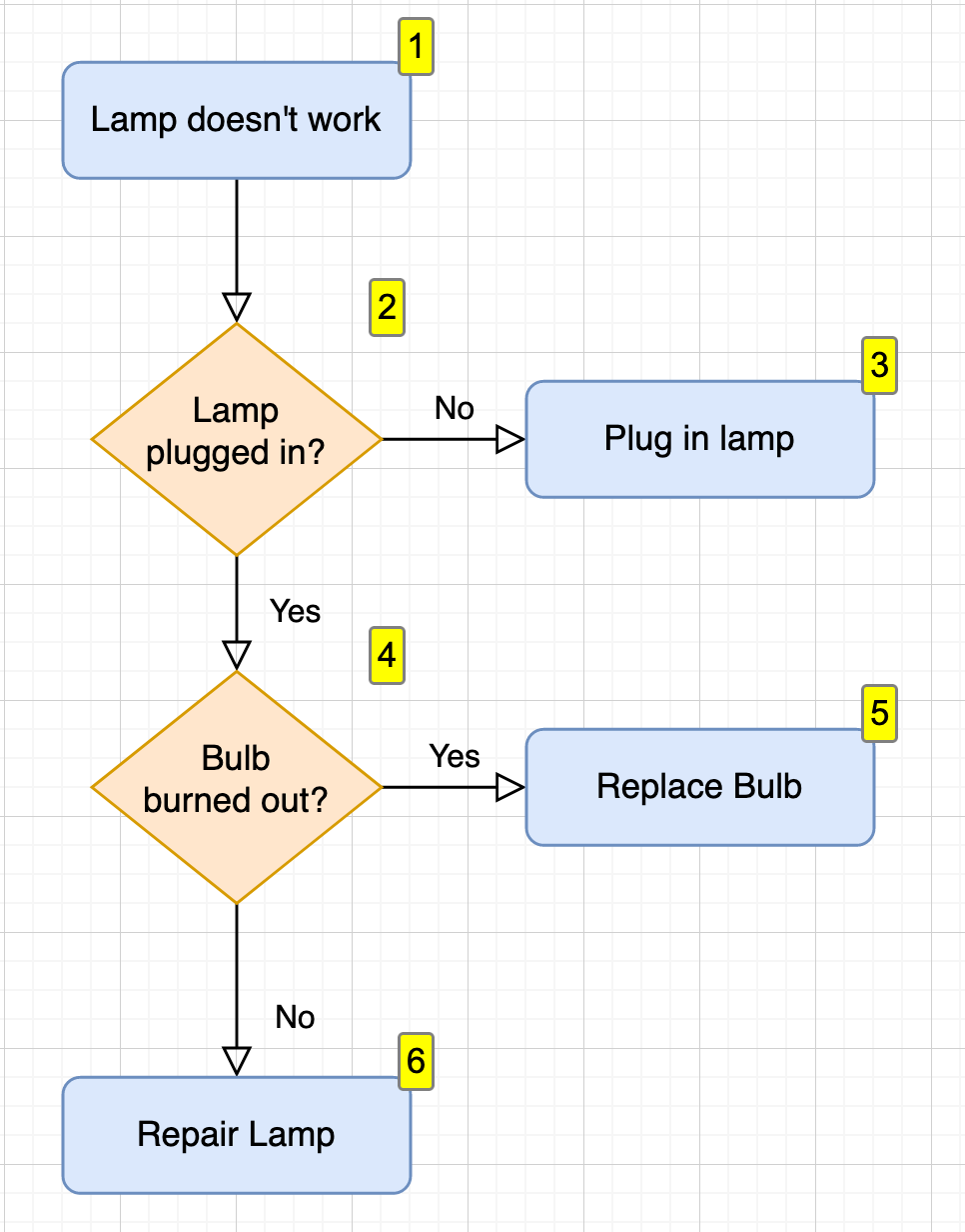
Online Flowchart Tool - Visual Paradigm Diagrams; Features; Flowchart Tool; Online Flowchart Tool. The easiest and most powerful Flowchart tool in the world. Make a Flowchart. Easy-to-Use online Flowchart tool. Flowchart is one of the most widely-used diagrams that represents an algorithm, workflow or process, showing the steps as boxes of various kinds, and their order by connecting ... Feature Tree Template | Creately Feature Tree Template. Use Creately's easy online diagram editor to edit this diagram, collaborate with others and export results to multiple image formats. Feature Trees are high-level models organizing features into feature groups, capturing the entire scope of a project into a single model. Network Diagram Features. NetworkMaps. Network Diagram Features. Network Diagrams on 3D. You can create and edit your network diagrams on a real 3D space. You are not limited by the space provided by traditional sheets. Instead you can span it on a full 3D space allowing you to create diagrams on a dimension never seen before. ER Diagram: Entity Relationship Diagram Model | DBMS Example ER Diagram stands for Entity Relationship Diagram, also known as ERD is a diagram that displays the relationship of entity sets stored in a database. In other words, ER diagrams help to explain the logical structure of databases. ER diagrams are created based on three basic concepts: entities, attributes and relationships.
Diagram features | MyScript Developer Diagram features. Features breakdown. Diagram; Text and shape simultaneous recognition Text and shapes can be drawn on the same canvas without having to switch tools. Connectors Different types of connectors can be drawn to link elements in a diagram. Labels can also be added to connectors. Intrusive Igneous Rocks - Diagram, Features, Types ... Here, in this article, we will learn about the intrusive volcano, intrusive forms, Intrusive rocks, its diagram, features, types, etc. Introduction A volcano is an opening on the surface of a planet that leads to the escape of various warmer materials such as lava, gases, dust, ashes, etc. from its interior. Online ERD Tool - Visual Paradigm Visual Paradigm's online ERD software makes database design fast and straight-forward. The ERD diagramming tool has all the ERD symbols and connectors you need to create professional, industry-standard ER model. No matter you want to create a conceptual, logical or physical data model, our online ERD tool just works perfectly. Data Flow Diagram - Everything You Need to Know About DFD Data Flow Diagram Levels. Context Diagram. A context diagram is a top level (also known as "Level 0") data flow diagram. It only contains one process node ("Process 0") that generalizes the function of the entire system in relationship to external entities. DFD Layers. Draw data flow diagrams can be made in several nested layers.

A successful Git branching model » nvie.com
Activity Diagram syntax and features - PlantUML.com PlantUML activity diagram syntax: You can have start, stop, labels, conditions, while loops, repeat loops, notes, partitions. Changing fonts and colors is also possible.
Feature Tree Template | Creately
Add Diagram Feature Capability By Attribute Rule (Network ... The diagram features that will be processed are queried from a network source class or object table by attributes. Learn more about the Add Diagram Feature Capability rule. Caution: This tool is a configuration and administration tool. Note:
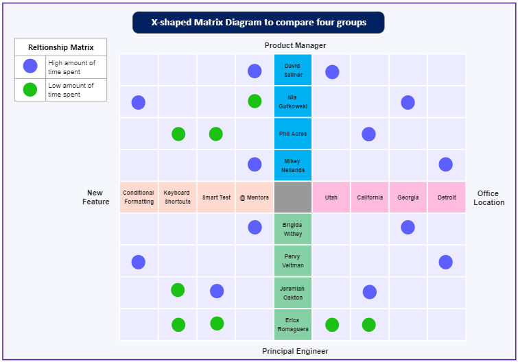
Matrix Diagram | EdrawMax
Online Genogram Software & Visual Solution Diagrams; Features; Genogram Software; Cloud-based Genogram Software. Create clear and professional Genogram in minutes. Make a Genogram. Create Genograms online. VP Online is the easiest Genogram software on the market today. Whether you're a beginner or a pro, to draw a Genogram is always simple and fast with VP Online's rich set of Genogram ...

What an Affinity Diagram is (and how to use it) - Miro
Features of phase diagram | bartleby Major features of the phase diagram. The major features of the phase diagram are: Triple point; Phase boundaries; Two-dimensional phase diagrams; Three-dimensional phase diagrams; Triple point. It is a point in the phase diagram that is characterized by an intersection of the equilibrium lines. A point where the three phases, solid, liquid, and ...
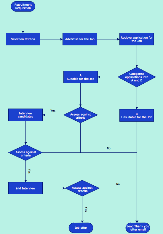
How to Draw a Good Diagram of a Business Workflow? | Features ...
Solved This diagram features a(n) cyclone, Southern ... Transcribed Image Textfrom this Question. This diagram features a (n) cyclone, Southern Hemisphere. anticyclone, Northern Hemisphere. cyclone, Northern Hemisphere. anticyclone, Southern Hemisphere.

tikz trees - Feature diagram in LaTeX? - TeX - LaTeX Stack ...
Component Diagram syntax and features - PlantUML.com In the diagram definition, like any other commands; In an included file; In a configuration file, provided in the command line or the Ant task. You can define specific color and fonts for stereotyped components and interfaces.
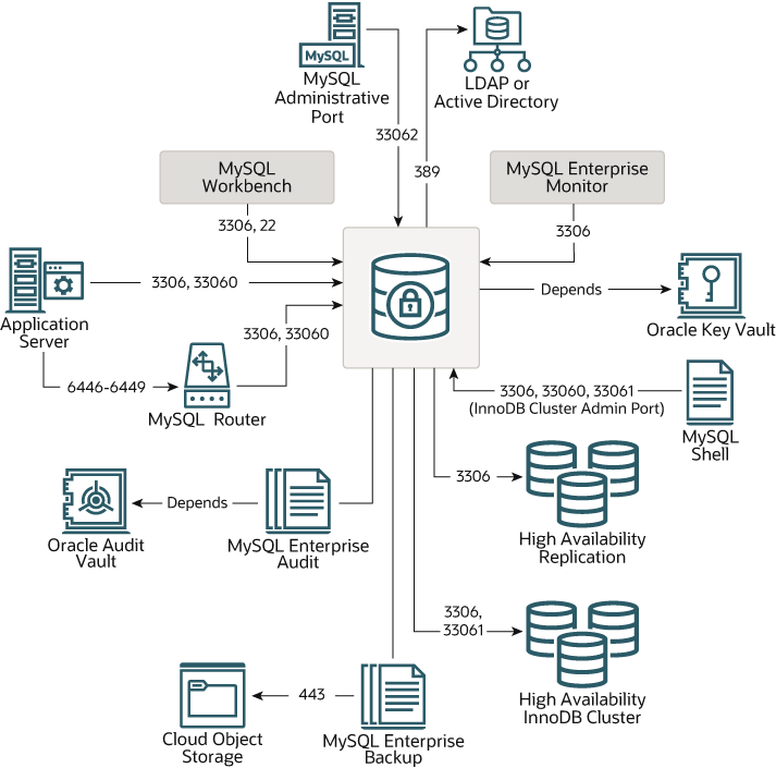
MySQL :: MySQL Port Reference :: 2 MySQL Port Diagram
ER Diagram (ERD) - Definition & Overview | Lucidchart The components and features of an ER diagram. ER Diagrams are composed of entities, relationships and attributes. They also depict cardinality, which defines relationships in terms of numbers. Here's a glossary: Entity. A definable thing—such as a person, object, concept or event—that can have data stored about it. Think of entities as nouns.
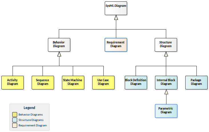
Getting to Know the SysML Diagrams | Enterprise Architect ...
UML Diagram - Everything You Need to Know About UML Diagrams UML Diagram What is a UML Diagram? UML is a way of visualizing a software program using a collection of diagrams. The notation has evolved from the work of Grady Booch, James Rumbaugh, Ivar Jacobson, and the Rational Software Corporation to be used for object-oriented design, but it has since been extended to cover a wider variety of software engineering projects.
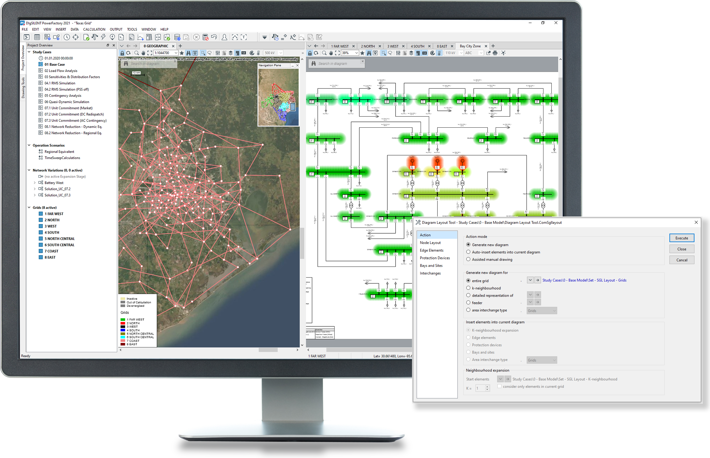
Network Diagrams and Graphic Features - DIgSILENT
What is Data Flow Diagram? - Visual Paradigm A context diagram gives an overview and it is the highest level in a data flow diagram, containing only one process representing the entire system. It should be split into major processes which give greater detail and each major process may further split to give more detail.

Overview | micro:bit
Diagram Software and Flowchart Maker More about the features of diagrams.net. Our range of diagrams.net and draw.io branded integrations. Google Workplace and Google Drive. Works with Google Drive and Google Workplace (G Suite). Use add-ons for Docs, Sheets and Slides. Sharepoint and OneDrive. Works with OneDrive and ...
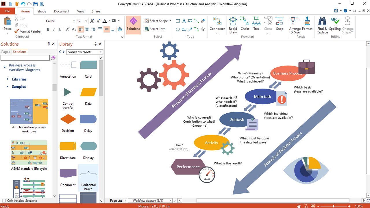
ConceptDraw DIAGRAM Features Overview | ConceptDraw
Features | Joystick Diagrams Features. The following is currently supported, you can check the roadmap out on Github. DCS World. Joystick Diagrams will automatically read your DCS World configurations, exporting out your favourite aircraft and their control mappings. You can also choose to only export certain aircraft.

Coast diagrams
Major Features of a Phase Diagram | Introduction to Chemistry The major features of a phase diagram are phase boundaries and the triple point. Phase diagrams demonstrate the effects of changes in pressure and temperature on the state of matter. At phase boundaries, two phases of matter coexist (which two depends on the phase transition taking place). The triple point is the point on the phase diagram at ...
Features Products Examples Pricing Class Diagram for Real ...
E-R Model Diagram and Extended E-R Feature in DBMS ... 4. Extended E-R Features: Specialization - The process of designating to sub grouping within an entity set is called specialization. In above figure, the "person" is distinguish in to whether they are "employee" or "customer". Formally in above figure specialization is depicted by a triangle component labelled (is a), means the customer is a person.
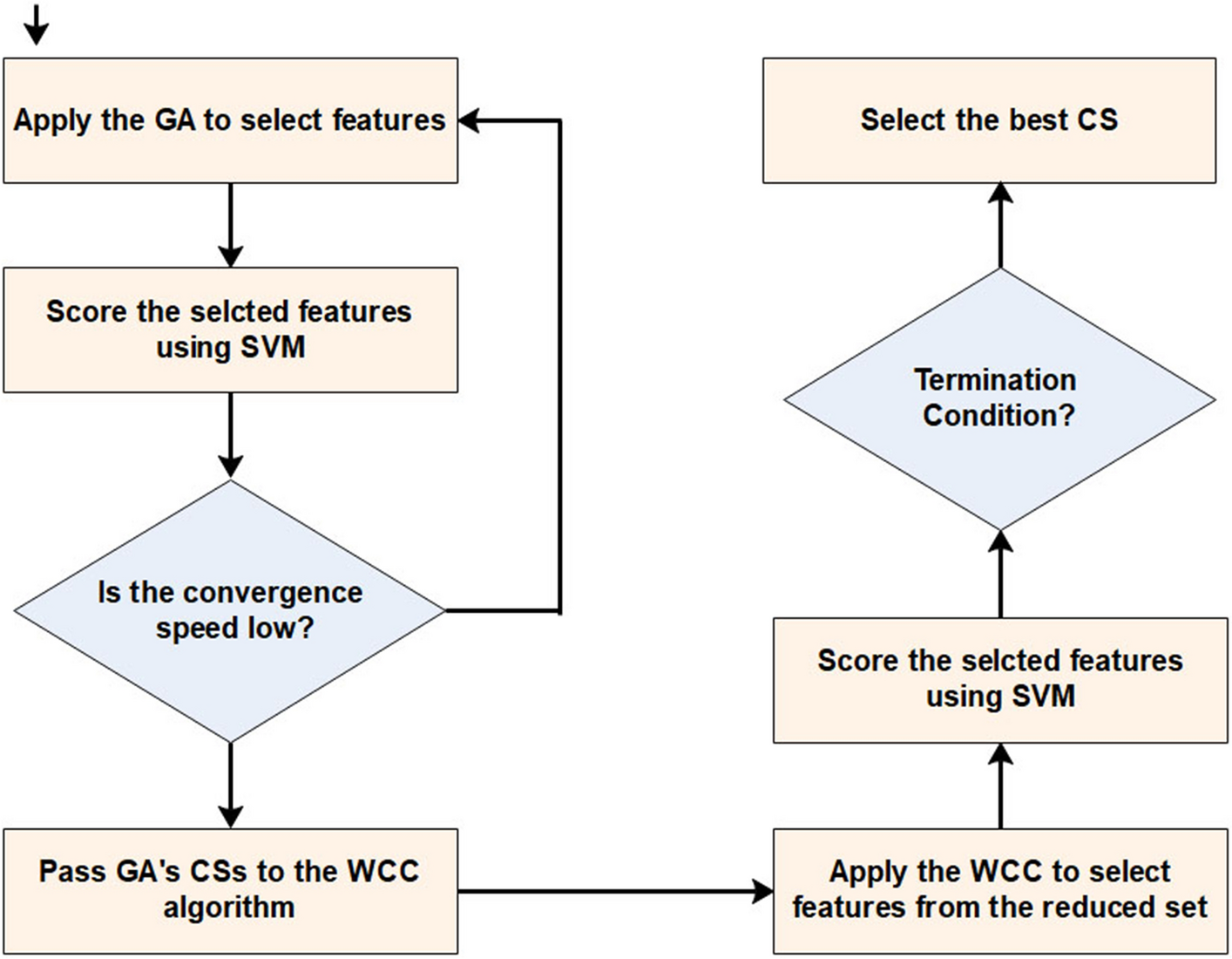
A machine learning method based on the genetic and world ...
Feature Diagram Editor - SDQ Wiki The feature diagram editor provides a layout algorithm which arranges the features in a hirarchical tree from top to bottom. If a new diagram is generated from an existing featuremodel, this layouting is applied automatically. In addition, it can be triggered manually in the right click context menu by selecting "Layout".

System feature diagram | Download Scientific Diagram
Add Remove Feature Rule (Network Diagram)—ArcGIS Pro ... Summary. Adds a diagram rule to automatically remove diagram features during diagram building based on an existing template. This rule removes diagram features based on different network source classes and object tables. Learn more about feature and nonspatial object removal in network diagrams.

Boost Your Time Series Forecasts Combining Gradient Boosting ...
What Is UML Diagram: Types and Features - CodeAvail What Is UML Diagram: Types & Features. One of the most common ways of presenting an in-depth visual representation for engineering and software development is Unified Modeling Language, also known as UML. Ideally, UML diagrams are correlated with OOP languages like JAVA and C++. It supports us in providing an overall software structure and the ...

uml - Use Case Diagram for Stack Overflow
Component Diagram - SmartDraw A component diagram, also known as a UML component diagram, describes the organization and wiring of the physical components in a system. Component diagrams are often drawn to help model implementation details and double-check that every aspect of the system's required functions is covered by planned development.

Enable feature reuse across accounts and teams using Amazon ...

ER Diagram (ERD) - Definition & Overview | Lucidchart

Build meeting features into your Amazon Chime SDK messaging ...
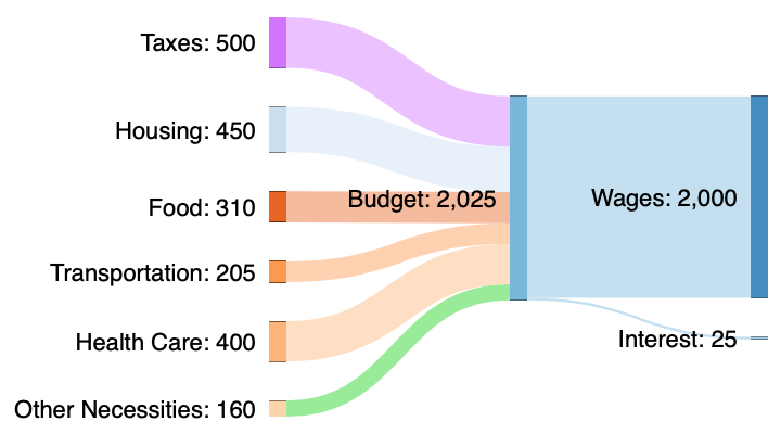
SankeyMATIC Manual: Miscellaneous Features
Billions of Miles of Data: The Autonomous Vehicle Training ...

Feature Diagram - an overview | ScienceDirect Topics

Disease progression and treatment response in data-driven ...
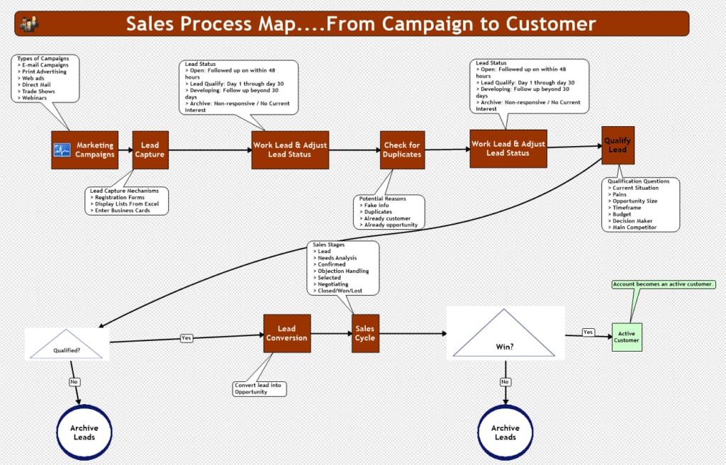
Workflow Diagram: A Complete Guide to Using Workflow Diagrams ...

Get Next Work feature | Pega Academy

Example of a Feature Model | Download Scientific Diagram

UML class diagrams in draw.io - draw.io

Diagrams Notepad - diagramming app for iOS and macOS

Major Features of a Phase Diagram | Introduction to Chemistry
Pixel phone hardware diagram - Pixel Phone Help
Graphity - Diagrams for Confluence | Atlassian Marketplace
Everyday maths 2 - OpenLearn - Open University
Learn how to diagram using diagrams.net features

What's coming in TensorFlow 2.0 — The TensorFlow Blog
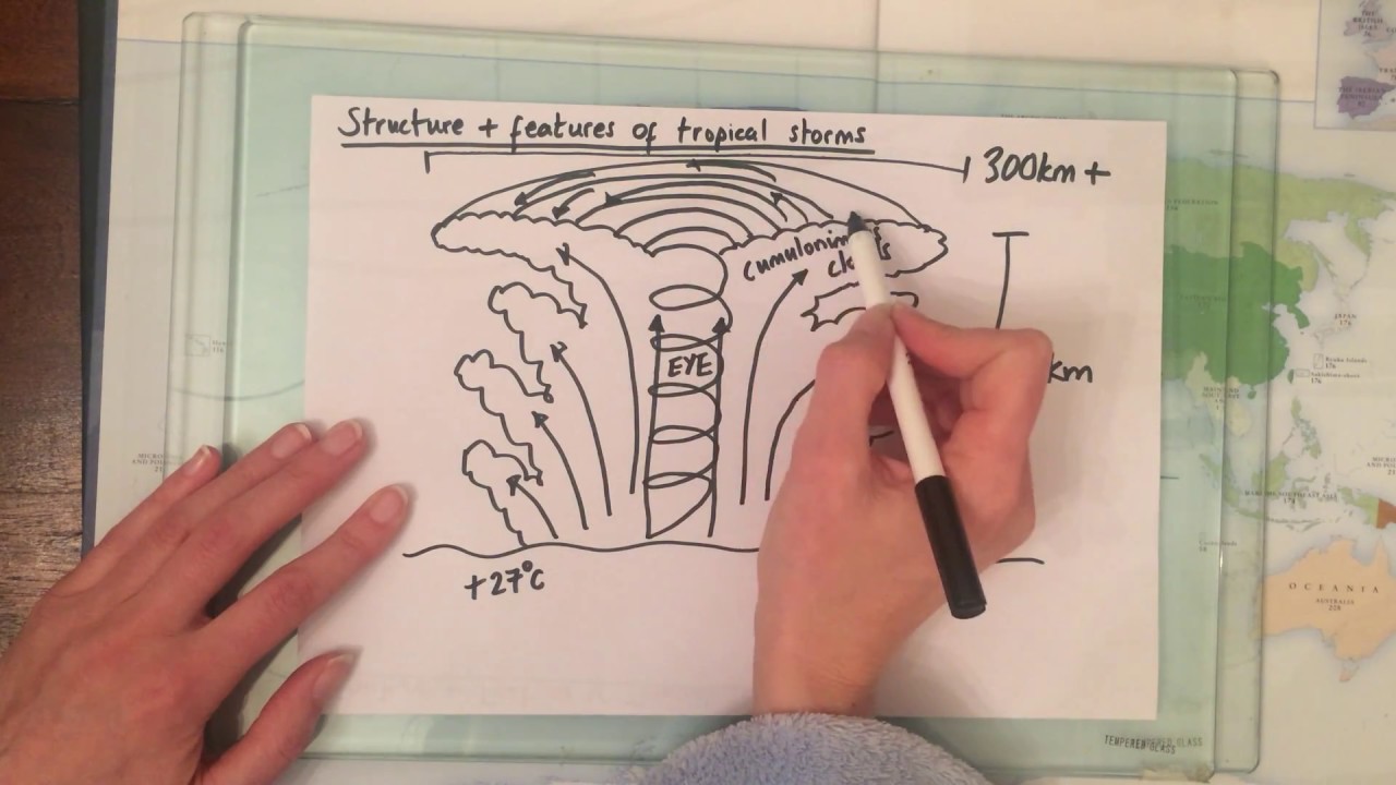
3.1.1.3 The structure and features of a tropical storm.
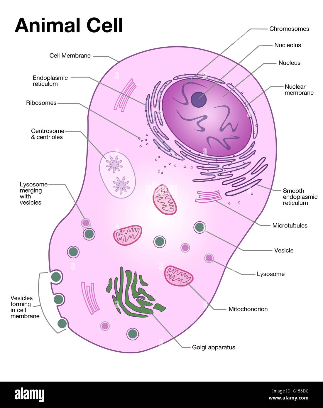
Diagram of a typical animal cell, with the important features ...
0 Response to "37 this diagram features a"
Post a Comment