38 state diagram digital logic
Digital electronics or digital (electronic) circuits are electronics that handle digital signals - discrete bands of analog levels - rather than by continuous ranges (as used in analogue electronics). All levels within a band of values represent the same numeric value. Because of this discretization, relatively small changes to the analog signal levels due to manufacturing tolerance ... A state diagram is a type of diagram used in computer science and related fields to describe the behavior of systems. State diagrams require that the system described is composed of a finite number of states; sometimes, this is indeed the case, while at other times this is a reasonable abstraction.Many forms of state diagrams exist, which differ slightly and have different semantics
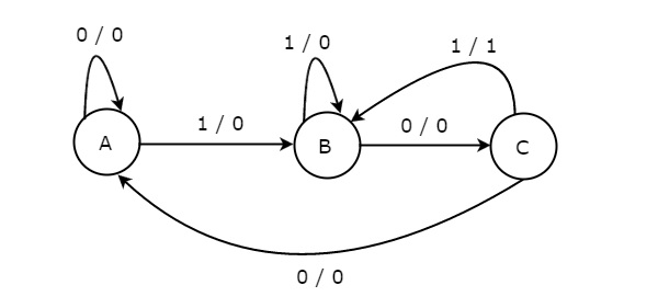
Digital Circuits - Finite State Machines. We know that synchronous sequential circuits change a f f e c t their states for every positive o r n e g a t i v e transition of the clock signal based on the input. So, this behavior of synchronous sequential circuits can be represented in the graphical form and it is known as state diagram.

State diagram digital logic
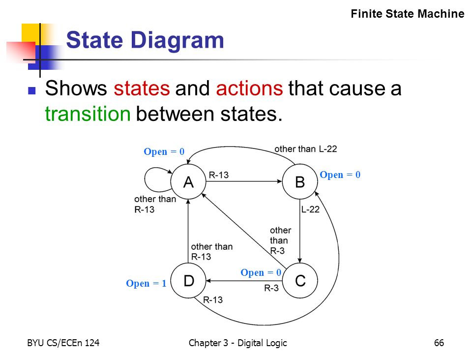
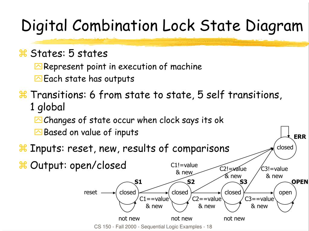
Digital combination lock state diagram • States: 5 states - represent point in execution of machine - each state has outputs • Inputs: reset, new, results of comparisons • Output: open/closed closed closed Moore Machine State Diagram, Mealy Machine State Diagram, Karnaugh Maps Digital Logic Design Engineering Electronics Engineering Computer Science State Diagrams and State Tables ... Fundamental to the synthesis of sequential circuits is the concept of internal states. At the start of a design the total ...
State diagram digital logic. A state diagram is used to represent the condition of the system or part of the system at finite instances of time. It's a behavioral diagram and it represents the behavior using finite state transitions. State diagrams are also referred to as State machines and State-chart Diagrams.These terms are often used interchangeably. So simply, a state diagram is used to model the dynamic behavior ... The Finite State Machine is an abstract mathematical model of a sequential logic function. It has finite inputs, outputs and number of states. FSMs are implemented in real-life circuits through the use of Flip Flops. The implementation procedure needs a specific order of steps (algorithm), in order to be carried out. LECTURE #17: Algorithmic State Machines (ASM's) EEL 3701: Digital Logic and Computer Systems Based on lecture notes by Dr. Eric M. Schwartz ASM Chart Basics: Example: In power distribution (supplying electricity to households and businesses), there is always the possibility of a fault. Faults are short-circuits to ground caused Spring 2010 CSE370 - XIV - Finite State Machines I 3 Example finite state machine diagram 5 states 8 other transitions between states 6 conditioned by input 1 self-transition (on 0 from 001 to 001) 2 independent of input (to/from 111) 1 reset transition (from all states) to state 100 represents 5 transitions (from each state to 100), one a self-arc
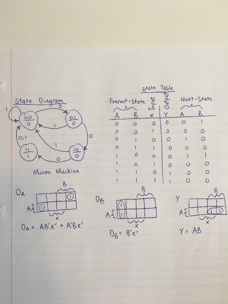
State reduction. While designing a sequential circuit, it is very important to remove the redundant states. The removal of redundant states will reduce the number of flip flops and logic gates, thereby reducing the cost and size of the sequential circuit. This is one of a series of videos where I cover concepts relating to digital electronics. In this video I talk about state tables and state diagrams. It is actually the graphical representation of logic circuits. The state diagram is a visual representation of how sequential circuits behave. It clearly depicts the transition of states from one state to the next, as well as the output for a given input. Each current state is represented by a circle in this graphic. The state diagram provides exactly the same information as the state table and is obtained directly from the state table. Example : This example is taken from P. K. Lala, Practical Digital Logic Design and Testing , Prentice Hall, 1996, p.155.
State and Finite State Machines Hakim Weatherspoon CS 3410, Spring 2013 Computer Science Cornell University See P&H Appendix C.7. C.8, C.10, C.11 A state diagram is a graphic representation of a state machine. It shows a behavioral model consisting of states, transitions, and actions, as well as the events that affect these. It's also one of the 14 Unified Modeling Languages (UML) used for specifying, visualizing, constructing, and documenting software systems. State Diagram — A state diagram represents states with circles, and transitions between states by arrows exiting one circle and arriving at another. A ... Design State Machine Diagram online. VP Online features a powerful UML diagram tool that lets you create state machine diagram and other UML diagrams easily and quickly. You can construct your diagrams with drag and drop, save your work in cloud workspace, output and share your design via numerous formats such as PNG, JPG, SVG, PDF, etc.
Uml State Machine Wikipedia
Figure 1: Digital lock logic as a owchart. be shown with four red LEDs. The enable status is shown with an amber LED, the lock/unlock status is shown with a green LED, and the alarm status is shown with a red LED. (b)Using your FSM from the Prelab, write code to implement the digital lock as a state machine. Sample code is included in Appendix A.

State Diagrams And State Tables
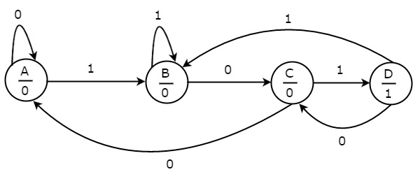
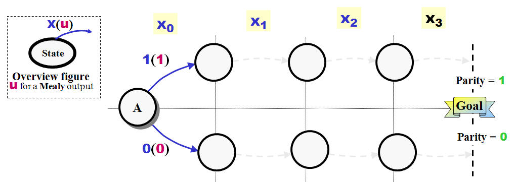
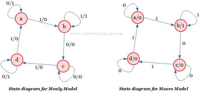
Prerequisite - Mealy and Moore machines A sequence detector is a sequential state machine that takes an input string of bits and generates an output 1 whenever the target sequence has been detected. In a Mealy machine, output depends on the present state and the external input (x). Hence, in the diagram, the output is written outside the states, along with inputs.
Converting State Diagrams To Logic Circuits
Example: State diagram from description •Draw the state diagram for a Moore Machine that detects a sequence of three or more consecutive 1's in a stream of bits coming through an input line. Chapter 5 ECE 2610 -Digital Logic 1 17
Digital Circuits Finite State Machines
DIGITAL CLOCK: Clocked Synchronous State Machines Digital Logic Design Engineering Electronics Engineering Computer Science ... Moore Machine State Diagram, Mealy Machine State Diagram, Karnaugh Maps ... THE LOGIC BLOCK: Analogue to Digital Conversion, Logic Element, Look-Up Table ...
Converting State Diagrams To Logic Circuits
Sequential circuit components: Circuit, State Diagram, State Table. Sequential circuit components: Flip-flop(s). Clock. Logic gates. Input. Output ...32 pages
Chapter 3 Digital Logic Ppt Download
The logic gate software has all the logic symbols you need to design any kind of logic model. No matter you want a logic diagram tool for teaching, or a logic circuit software for engineering purposes, our online logic diagram creator just works perfectly. Besides the logic diagram tool, we've put together some logic diagram templates to help ...

Digital Logic Circuits Design Of Sequential Circuits Vidyarthiplus V Blog A Blog For Students
Combinational Logic. Combinational logic is a digital logic that implements Boolean circuits where the output is a function of the present input alone. The logical function of the current input state, logic "0" or logic "1", at any given instant time determines the outputs of combinational logic.
Solved Digital Logic Problem Given The State Diagram State Chegg Com
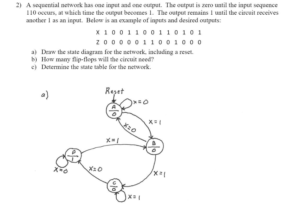
• From a state diagram, a state table is fairly easy to obtain. • Determine the number of states in the state diagram. • If there are states and 1-bit inputs, then there will be rows in the state table. • Example: If there are 3 states and 2 1-bit inputs, each state will have possible inputs, for a total of 3*4=12 rows.
What Is The Difference Between A State Diagram And A Circuit Diagram Quora
Digital Design Sequential Logic Design -- Controllers First (bad) attempt to implement the laser surgery system. What's so baaaaad about it? 9 Digital Design Sequential Logic Design -- Controllers: FSM A simple state diagram and the timing diagram describing the state diagram's behavior. "clk^" represents the rising edge of the clock ...

State Tables And State Diagrams
As you know, the design of a synchronous state machine involves combinational logic to determine the next state and the output from the current state and the ...
Ppt Sequential Logic Examples Powerpoint Presentation Free Download Id 312781
Finite State Machines • Design methodology for sequential logic-- identify distinct states-- create state transition diagram-- choose state encoding-- write combinational Verilog for next-state logic-- write combinational Verilog for output signals • Lots of examples 6.111 Fall 2017 Lecture 6 1
Unified Modeling Language Uml State Diagrams Geeksforgeeks
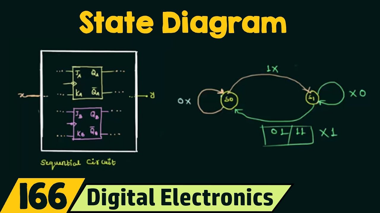
Digital Electronics: Introduction to State Table, State Diagram & State EquationContribute: http://www.nesoacademy.org/donateWebsite http://www.nesoacademy...

K5 Digital Electronics Serial Two S Complementer Circuit
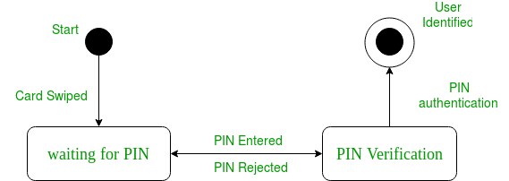
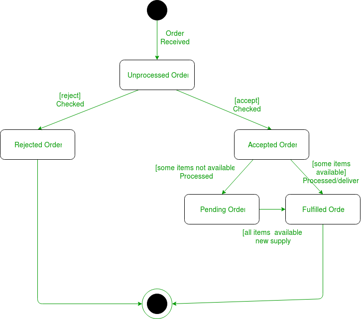
Initial and Final States. The initial state of a state machine diagram, known as an initial pseudo-state, is indicated with a solid circle. A transition from this state will show the first real state The final state of a state machine diagram is shown as concentric circles. An open loop state machine represents an object that may terminate before the system terminates, while a closed loop ...

Digital Logic State Tables And State Diagrams Youtube
designed. Alternatively obtain the state diagram of the counter. • Determine the number and type of flip-flop to be used. • From the excitation table of the flip-flop, determine the next state logic. • From the output state, use Karnaugh map for simplification to derive the circuit output functions and the flip-flop output functions.

Welcome To Real Digital
State Diagrams and State Tables ... Fundamental to the synthesis of sequential circuits is the concept of internal states. At the start of a design the total ...
Digital Circuits Finite State Machines
Moore Machine State Diagram, Mealy Machine State Diagram, Karnaugh Maps Digital Logic Design Engineering Electronics Engineering Computer Science
1
Digital combination lock state diagram • States: 5 states - represent point in execution of machine - each state has outputs • Inputs: reset, new, results of comparisons • Output: open/closed closed closed

Cpen Digital System Design Chapter 5 Sequential Circuits Sequential Circuit Design C Gerousis C Logic And Computer Design Fundamentals 4 Rd Ed Ppt Download
The Digital Logic Shown In The Figure Satisfies The Given State Diagram When Q1 Is Connected To Input A Of The Xor Gate Sarthaks Econnect Largest Online Education Community
Unified Modeling Language Uml State Diagrams Geeksforgeeks

State Diagrams And State Tables
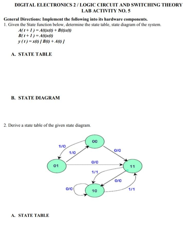
Solved Digital Electronics 2 Logic Circuit And Switching Chegg Com
Introduction To State Table State Diagram State Equation Youtube

Dense State Assignment About World War 2 For Kids Homework
Converting State Diagrams To Logic Circuits
State Diagrams

Atm Machine Digital Logic Design Assignment Docsity

State Tables And State Diagrams

Cpr E 281 Digital Logic Instructor Alexander Stoytchev
Finite State Machines Sequential Circuits Electronics Textbook

Fundamentals Of Digital Logic Chapter2 Digital Logic Digital
Solved Digital Logic Explain The Steps On How To Get To The Chegg Com

Sequential Circuits An Overview Sciencedirect Topics
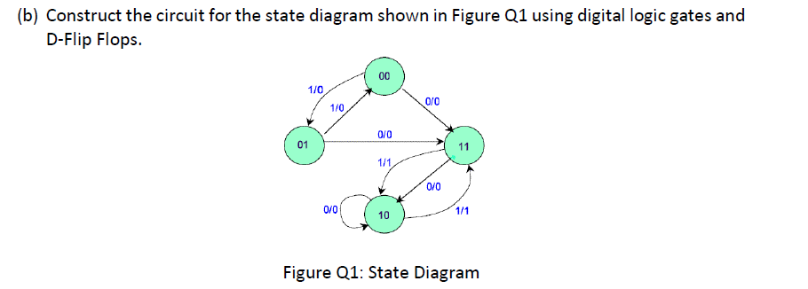
Solved B Construct The Circuit For The State Diagram Shown Chegg Com

Sequential Logic Circuits

Digital Logic Circuits Design And Analysis Of Counters Vidyarthiplus V Blog A Blog For Students

Welcome To Real Digital
State Diagram And State Table With Solved Problem On State Reduction
0 Response to "38 state diagram digital logic"
Post a Comment