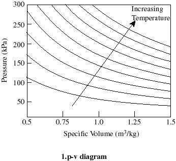
40 pv diagram constant temperature
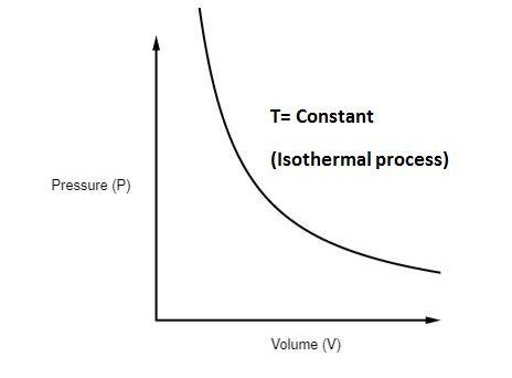
Note that such a line on a P-V diagram is known as an isotherm, which is a line of constant temperature. Chapter 14 – Thermal Physics: A Microscopic View. Page ...2 pages temperature) constant, the gas must be absorbing heat from the water. As long as the energy lost (by the gas doing work) equals the heat gained from the water, the internal energy will not change and the temperature stays the same. U=Q W U=−W W U=0 The PV diagram we get shows a curved line as the pressure and volume both change.
pV γ=constant =1 1 =constant pV γ pVγ 1 constant 2 2 1 1 1 = = T Vγ− T V γ− pV =nRT During an adiabatic expansion process, the reduction of the internal energy is used by the system to do work on the environment. During an adiabatic compression process, the environment does work on the system and increases the internal energy.

Pv diagram constant temperature
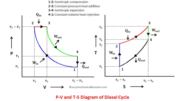
Q = 0, the P-V diagram is an interesting line, given by: For a monatomic ideal gas: Applying the first law: EW. int. PV. γ =constant γ= P V. C C. γ== = 5/2 5 3/2 3. P V. C R CR. 1. Note that W = area under the P-V curve is > 0 in the process 1→2, but < 0 in 2→1. 2. 18. A container of monatomic ideal gas contains just the right number of ... During this process, temperature remains constant (T = C). The law for the process is PV = C and is represented by means of a curve as shown on the PV-diagram. It is represented by means of a horizontal line on T-S diagram. (a) Work Done: The work done in a non-flow system. (b) Change in IE: (c) Heat Transferred: 4. Reversible Adiabatic Process:
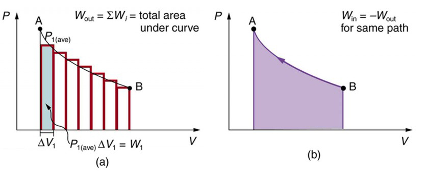
Pv diagram constant temperature. 15:24Why work from expansion is the area under the curve of a PV-diagram. ... PV = constant if temperature is ...7 Aug 2013 · Uploaded by Khan Academy In P-V graph of constant temperature pressure and volume are variables. But since temperature is constant the ideal gas law can be modified; PV= nRT. now ...3 answers · Top answer: * Constant temperature means an isothermal process. • PV=nRT 1. 1. This is the ideal ... PV Diagrams. We can examine aspects of the behavior of a substance by plotting a graph of pressure versus volume, called a PV diagram.When the substance behaves like an ideal gas, the ideal gas law describes the relationship between its pressure and volume. I doubt this question has been addressed properly before, but if there are similar answers, do direct them to me. I am currently studying the First Law of Thermodynamics, which includes the p-V di...
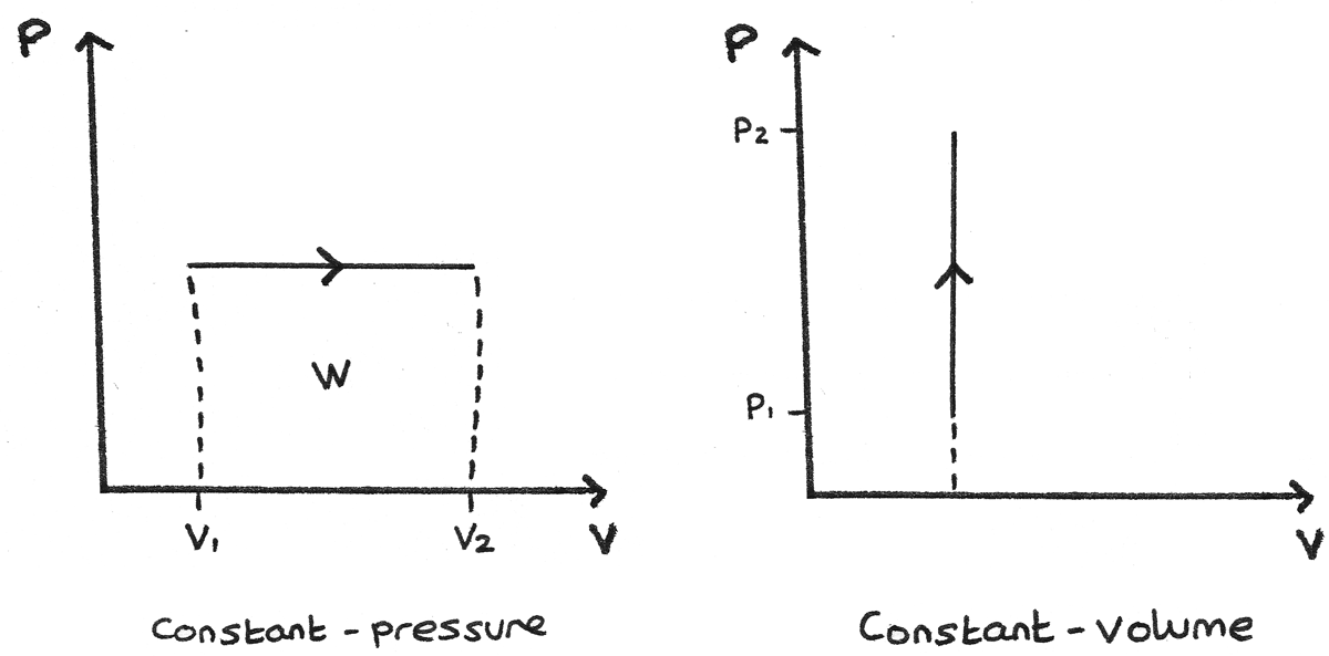
20:17This physics video tutorial provides a basic introduction into PV diagrams. ... (Constant Temperature) Process ...4 Dec 2017 · Uploaded by The Organic Chemistry Tutor $$ Q = \Delta U + p\Delta V $$ P-V Diagrams. A pressure-volume diagram, also known as an indicator diagram is used to show changes to the pressure and volume in thermodynamic cycles. The area under a p-V curve represents the work done on or by a gas. Some p-V diagrams are shown below: Constant Pressure and Constant Volume The PV diagram models the relationship between pressure (P) and volume (V) for an ideal gas.An ideal gas is one that never condenses regardless of the various changes its state variables (pressure, volume, temperature) undergo. In addition, the processes plotted on PV diagrams only work for a closed system (in this case the ideal gas), so there is no exchange of matter, but still an exchange ... A system can be described by three thermodynamic variables — pressure, volume, and temperature. Well, maybe it's only two variables. With everything tied together by the ideal gas law, one variable can always be described as dependent on the other two.
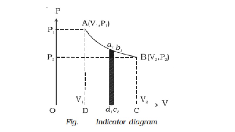
A convenient way to visualize these changes in the pressure and volume is by using a Pressure Volume diagram or PV diagram for short. Each point on a PV diagram corresponds to a different state of the gas. The pressure is given on the vertical axis and the volume is given on the horizontal axis, as seen below. During this process, temperature remains constant (T = C). The law for the process is PV = C and is represented by means of a curve as shown on the PV-diagram. It is represented by means of a horizontal line on T-S diagram. (a) Work Done: The work done in a non-flow system. (b) Change in IE: (c) Heat Transferred: 4. Reversible Adiabatic Process: Q = 0, the P-V diagram is an interesting line, given by: For a monatomic ideal gas: Applying the first law: EW. int. PV. γ =constant γ= P V. C C. γ== = 5/2 5 3/2 3. P V. C R CR. 1. Note that W = area under the P-V curve is > 0 in the process 1→2, but < 0 in 2→1. 2. 18. A container of monatomic ideal gas contains just the right number of ...
An Ideal Gas At A Given State Expands To A Fixed Final Volume First At Constant Pressure And Then At Constant Pressure And Then At Constant Temperature How Is Work Calculated For
1
1
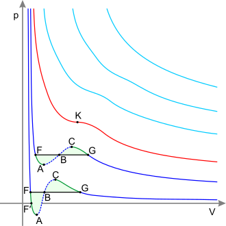
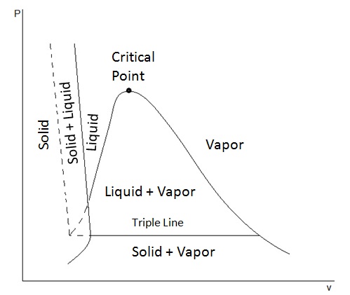
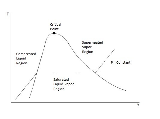
Critical Point Thermodynamics Wikipedia
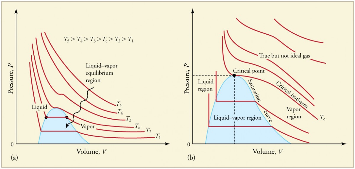
Phase Changes Physics
How To Calculate The Temperature In A P V Diagram Quora

Understanding The Pressure Volume Diagrams Omnia Mfg

The P V Diagram Of Above Process
Ecoursesonline Iasri Res In
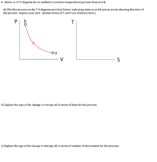
Solved Below Is A P V Diagram For An Isotherm Constant Chegg Com

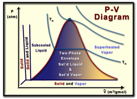
Properties Of Pure Substances First Law Of Thermodynamics
Pv Diagram For Pure Systems Png 520 Phase Behavior Of Natural Gas And Condensate Fluids
The First Law Of Thermodynamics And Some Simple Processes Physics

Thermodynamics Ebook Property Diagrams
T V
What Other Thermodynamic Properties Besides Temperature And Pressure May Be Graphed In Phase Diagrams Socratic
First Law And P V Diagrams Revise Im

A Closed Tank Contains 2 Kg Of Saturated Liquid Water Initially At 80 Circ C State 1 Heat Transfer Occurs And The Tank Is Allowed To Expand Such That The Liquid Vapor Mixture Remains At
Unified Engineering Thermodynamics Chapter 2
Diesel Cycle Process With P V And T S Diagram Mechanical Booster

Ctiemt Cse 2012 2016 Eme Notes 2nd Chapter
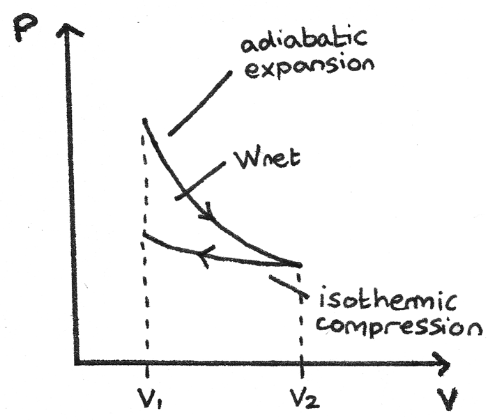
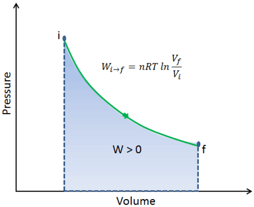
4 Pv Diagram The Work W At Constant Temperature Download Scientific Diagram

Chapter 3a The First Law Closed Systems Energy Updated 1 17 11

Pv Vs P Graph For A Gas At Constant Temperature Is A Hyperbolic B Parabolic C A Straight Line Brainly In

What Are Pv Diagrams Article Khan Academy
What Is The Isothermal Process Class 11 Physics Cbse
Ecoursesonline Iasri Res In

Shortcuts To Convert P V Diagram Into T S Diagram Exergic
First Law And P V Diagrams Revise Im
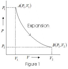
P V Indicator Diagram With Solved Examples
Ch2 Lesson B Page 6 P V Phase Diagram
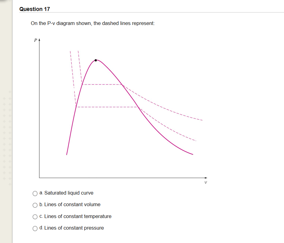
Solved Question 17 On The P V Diagram Shown The Dashed Chegg Com
Phase Changes S B A Invent
Isothermal Expansion Isothermal Compression Nuclear Power Com

Pressure Volume Diagram Energy Education

What Are Pv Diagrams Article Khan Academy

Isothermal Compression An Overview Sciencedirect Topics

In The Process Illustrated By The Pv Diagram The Temperature Of The Ideal Gas Remains Constant At 116 Circ C A How Many Moles Of Gas Are Involved B What Volume Does
Indicator Diagram P V Diagram
Solved A System Consists Of A Saturated Liquid Vapor Mixture Heat Is Added To The System At Constant Temperature The Quality A Increases B Course Hero
0 Response to "40 pv diagram constant temperature"
Post a Comment