41 finite state machine diagram
A finite state machine (fsm) diagram, also called a statechart diagram, is a directed graph. The nodes represent internal states of some abstract machine. UML Tutorial: Finite State Machines Robert C. Martin Engineering Notebook Column C++ Report, June 98 In my last column I presented UML sequence diagrams. Sequence diagrams are one of the many tools in UML that support dynamic modeling. In this column we will be discussing another kind of dynamic modeling tool in UML, the Finite State Machine (FSM).
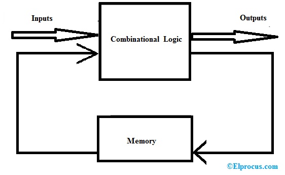
314 FINITE STATE MACHINE: PRINCIPLE AND PRACTICE d q state register Moore output logic Mealy output logic Mealy output Moore output next-state logic state_next state_reg input clk Figure 10.1 Block diagram of an FSM. of a system. As time progresses, the FSM transits from one state to another. The new state

Finite state machine diagram
FSM Finite State Machine Questions and Answers. 1. Design a finite state machine FSM for a serial two’s complement block and also draw the logic diagram associated with it by using D-flipflop. The main logic behind this is, start from the least significant bit and retain the bits until and first 1-bit has occurred. • A finite state machine is a device, or a model of a device, which has a finite number of states it can be in at any given time and can operate on input to either make transitions from one state to another or to cause an output or action to take place. A finite state machine can only be in one state at any moment in time. In automata theory, there are two basic types of finite-state machines (FSM). ... Be aware that both state diagrams, the Moore machine above and the Mealy ...
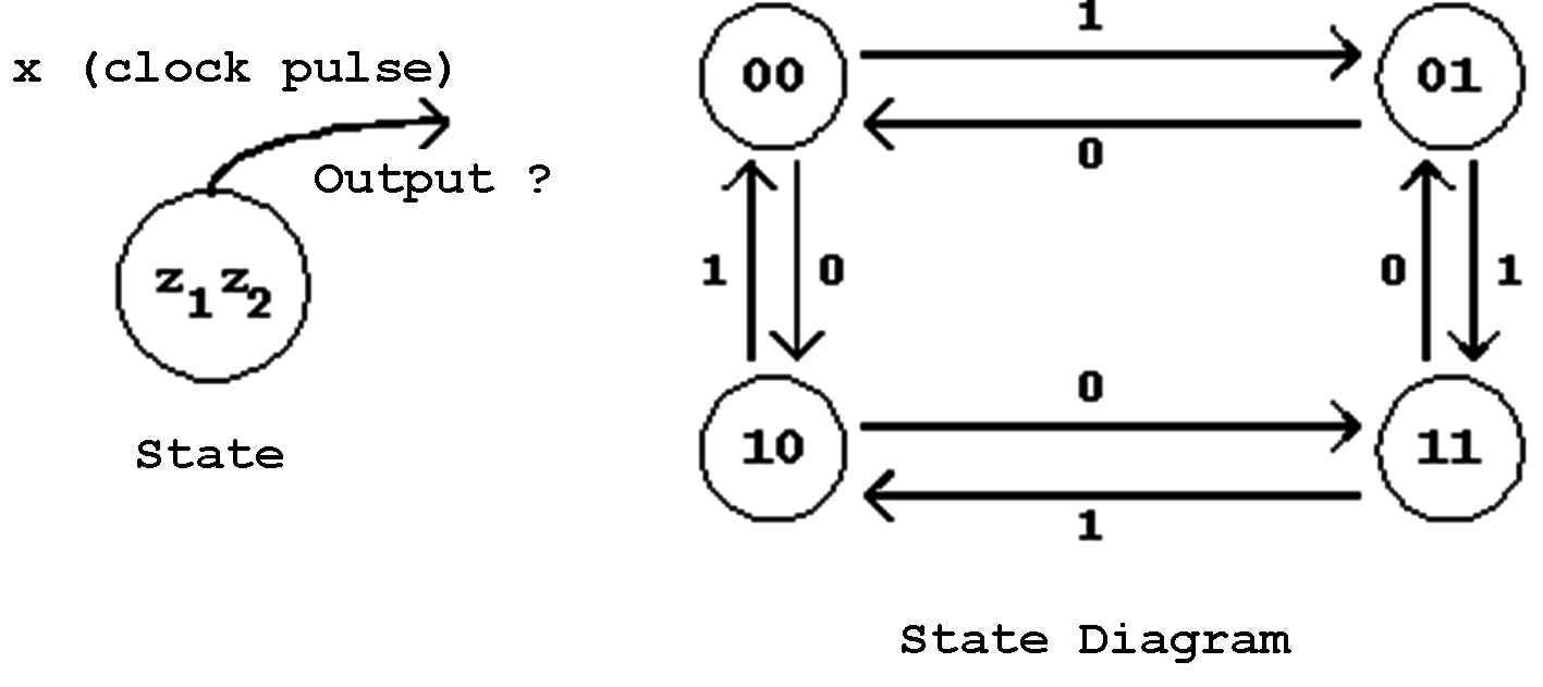
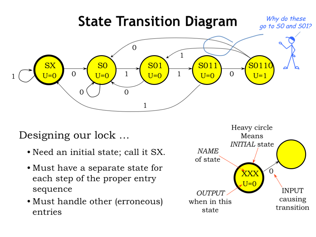
Finite state machine diagram. Behavioral state machine is specialization of behavior and is used to specify discrete behavior of a part of designed system through finite state transitions. State Machine Diagrams ... A state machine diagram models the behaviour of a single object, specifying the sequence of events that an object goes through during ... Draw the state transition diagram (states & arrows) that expresses this FSM. Use the notation AB for inputs (10 means A = 1 and B = 0). (1) Draw a state diagram (2) Write output and next-state tables (3) Encode states, inputs, and outputs as bits (4) Determine logic equations for next state and outputs (5) Draw the circuit Finite State Machines • Finite State Machines (FSMs) are a useful abstraction for sequential circuitswith centralized “states” of operation • At each clock edge, combinational logic computes outputsand next stateas a function of inputsand present state Combinational Logic Registers Q D CLK inputs + present state outputs + next state n n
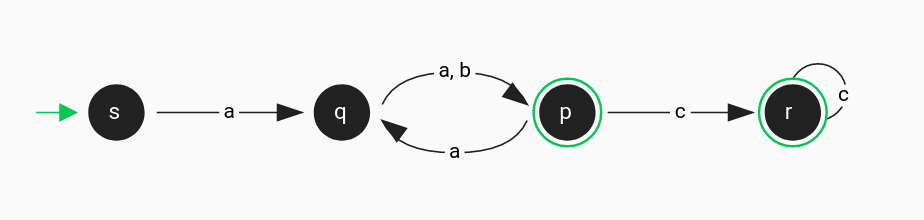
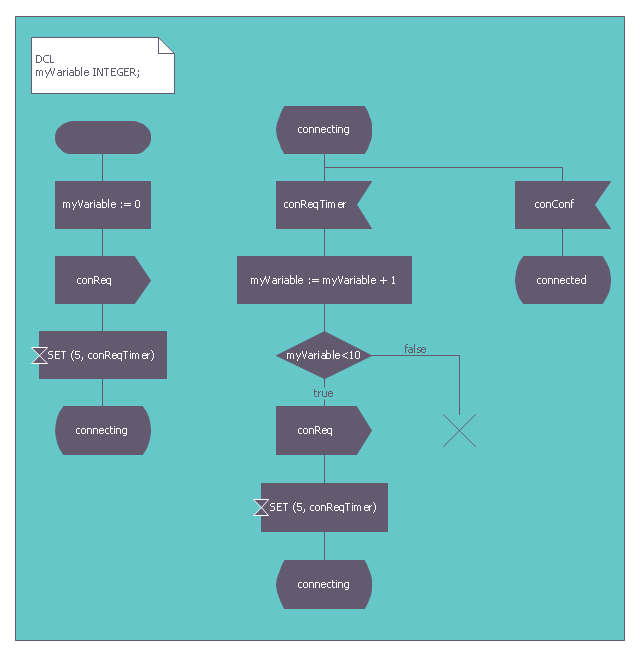
A state diagram, sometimes known as a state machine diagram, is a type of behavioral diagram in the Unified Modeling Language (UML) that shows transitions ... Other state diagrams — The turnstile state machine can also be represented by a directed graph called a state diagram (above). Each state is represented by ...Extended finite-state machine · Virtual finite-state machine TRANSLATE FROM DIAGRAM FINITE STATE MACHINES •STATE DIAGRAMS •STATE TABLES-INTRODUCTION-BIT FLIPPER EX. • From a state diagram, a state table is fairly easy to obtain. • Determine the number of states in the state diagram. • If there are states and 1-bit inputs, then there will be rows in the state table. UML State Machine Diagrams (or sometimes referred to as state diagram, state machine or state chart) show the different states of an entity. State machine diagrams can also show how an entity responds to various events by changing from one state to another. State machine diagram is a UML diagram used to model the dynamic nature of a system.
Finite-State Machines 473 q Direction of tape motion Direction of tape motion reading writing Figure 192: Finite-state machine viewed as a stationary-head, moving-tape, device Since the motion of the head over the tape is strictly one-way, we can abstract away the idea of a tape and just refer to the input sequence read and the output sequence ... Spring 2010 CSE370 - XIV - Finite State Machines I 3 Example finite state machine diagram 5 states 8 other transitions between states 6 conditioned by input 1 self-transition (on 0 from 001 to 001) 2 independent of input (to/from 111) 1 reset transition (from all states) to state 100 represents 5 transitions (from each state to 100), one a self-arc In automata theory, there are two basic types of finite-state machines (FSM). ... Be aware that both state diagrams, the Moore machine above and the Mealy ... • A finite state machine is a device, or a model of a device, which has a finite number of states it can be in at any given time and can operate on input to either make transitions from one state to another or to cause an output or action to take place. A finite state machine can only be in one state at any moment in time.
Game Ai Finite State Machines Game Development
FSM Finite State Machine Questions and Answers. 1. Design a finite state machine FSM for a serial two’s complement block and also draw the logic diagram associated with it by using D-flipflop. The main logic behind this is, start from the least significant bit and retain the bits until and first 1-bit has occurred.
A Finite State Machine Model Creately

Sekedar Informasi Finite State Machine Pada Game

File Border Gateway Protocol Finite State Machine Diagram Png Wikimedia Commons

Finite State Machine Wikipedia
An010 Finite State Machines Datasheets Particle
Finite State Machines Sequential Circuits Electronics Textbook
Finite State Machine Our Pattern Language

Software Design Of State Machines Embedded Com

Finite State Machines

Creating A Chatbot Using A Finite State Machine Hamid Adelyar
3

Arduino State Machine Tutorial Microcontroller Tutorials

Converting Finite State Machine Diagram Into Verilog Code Stack Overflow

Problem Solving Finite State Machines Wikibooks Open Books For An Open World

State Diagram Of The Control Unit Finite State Machine Download Scientific Diagram
2

Mesin Finite State Teori Dan Implementasi

The State Pattern Exemplified In Typescript Dev Community
A Finite State Machine Model Creately
Uml State Machine Diagram Training Material

Finite State Machine An Overview Sciencedirect Topics

Desvita Blog Finite State Machine Fsm Dan Pseucode

Synthesis Of Controllers From Finite State Stack Machine Diagrams Semantic Scholar

Software Design Of State Machines Embedded Com
Digital Design Finite State Machines

File Finite State Machine State Diagram Png Wikimedia Commons
Finite State Machine Diagram Of Dialog Flow Download Scientific Diagram
Finite State Machine Fsm Types Properties Design And Applications
Finite State Machines An Example Based Introduction Level Up Coding

Finite State Machines Part 2 Explicit Typed State Transitions Oskar Wickstrom
Finite State Machine Diagram 1000x597 Png Download Pngkit
Mesin Finite State Wikipedia Bahasa Indonesia Ensiklopedia Bebas
Developing Robust Finite State Machines Code With Lint Tools
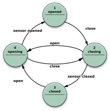
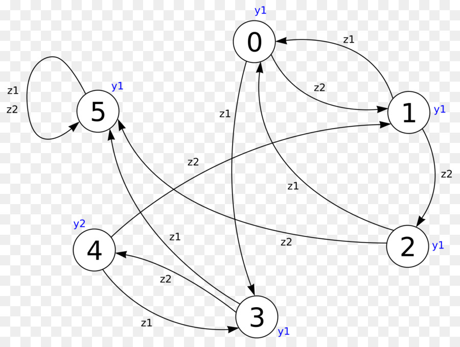
Finite State Machine Fsm Finite State Machine State Machine Diagram Finite State Machine

State Machine Diagram Uml 2 Tutorial Sparx Systems
L06 Finite State Machines

Finite State Machine Wikipedia The Free Encyclopedia Finite State Machine State Diagram Diagram
Moore Mesin Finitestate Mesin Mesin Gambar Png
2
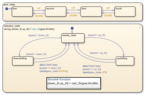
Model Finite State Machines Matlab Simulink
0 Response to "41 finite state machine diagram"
Post a Comment