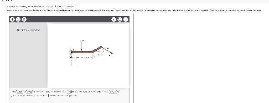
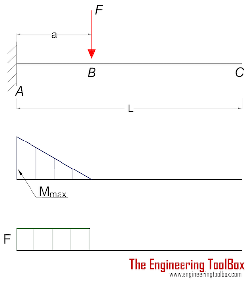
35 draw the free-body diagram for the cantilevered beam. a is the a fixed support.
... and shear force diagram calculator bendingmomentdiagram offers a range of engineering tools including a free bending moment diagram calculator moment ...
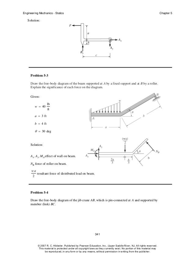
FREE-BODY DIAGRAMS (Section 5.2) 2. Show all the external forces and couple moments. These typically include: a) applied loads, b) support reactions, and, c) the weight of the body. Idealized model Free-body diagram (FBD) 1. Draw an outlined shape. Imagine the body to be isolated or cut "free" from its constraints and draw its outlined shape.
... Arrangements for testing electric properties; Arrangements for locating electric faults; Arrangements for electrical testing characterised by what is ...
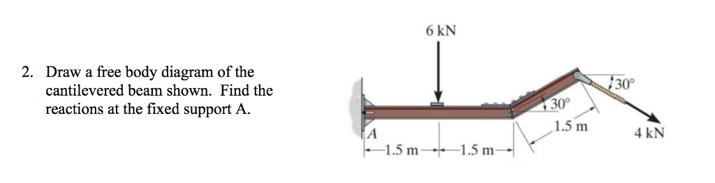
Draw the free-body diagram for the cantilevered beam. a is the a fixed support.
Draw the free-body diagram for the following problems. a) The rod in Prob. $5-44$ b) The hand truck and load when it is lifted in Prob. $5-45$ c) The beam in Prob. $5-47$ d) The cantilever footing in Prob. $5-51$
A short video to show how to form an imaginary cut and draw a free body diagram of a simply supported beam with a point load.Related videos:Reactions of a Si...
4.4 Moment Diagrams by Parts The moment-area method of finding the deflection of a beam will demand the accurate computation of the area of a moment diagram, as well as the moment of such area about any axis. To pave its way, this section will deal on how to draw moment diagrams by parts and to calculate the moment of such diagrams about
Draw the free-body diagram for the cantilevered beam. a is the a fixed support..
Draw the free body diagram for the cantilevered beam a is the a fixed support. For each beam shown draw the free body diagram and discuss the support reactions present. Figure a move the mouse over the figure to see the free body diagram in figure a the beam is supported by a pin or hinge at point a and by a roller at d.
Free online beam calculator for generating the reactions, calculating the deflection of a steel or wood beam, drawing the shear and moment diagrams for the beam. This is the free version of our full SkyCiv Beam Software. This can be accessed under any of our Paid Accounts, which also includes a full structural analysis software.
After designing a free body diagram of a beam, click on Run Analysis button or press F5 key and let the software analyze the diagram drawn by you.
https://goo.gl/P5AUbb for more FREE video tutorials covering Engineering Mechanics (Statics & Dynamics)The key objective of this video is to consider support...
directly on the diagram. Pertinent dimensions may also be represented for convenience. Note, however, that the free-body diagram serves the purpose of focusing accurate attention on the action of the external forces; therefore, the diagram should not be cluttered with excessive information. Force arrows
Draw free body diagram for the segment of the beam. Show S & M at the cut section, 5. Write the equilibrium equations, obtainable from the free body diagram, 6. Solve the equilibrium equations for the Shear Force S and the Bending Moment M, 7. Plot the expressions for S and M for the segment. It is desirable to draw the shear force diagram ...
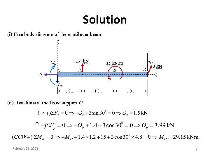
... the case of cantilever shown in figure 5-1(a), there is no horizontal force and hence the fixed support will have only two reaction components (one ...
1. Draw Free Body Diagram 2. Apply Equilibrium Example: Cantilevered Flag Figure M4.3-8 Geometry and free body diagram of cantilevered flag z x ~ ~ ~ • x z m = mass/unit length mg H A V A M A f f L L FREE BODY DIAGRAM:
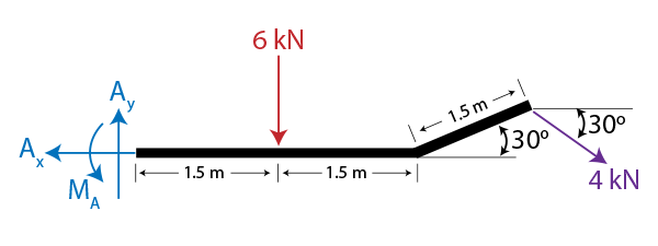
Draw the free body diagram for the cantilevered beam a is the a fixed support. Draw the vectors starting at the black dots. Our first step is to draw a free body diagram like so. Determine the components of the support reactions at the fixed support a on the cantilevered beam. A y 4knd 0 m a.
• Create a free-body diagram for the complete frame and solve for the support reactions. • Define a free-body diagram for member BCD. The force exerted by the link DE has a known line of action but unknown magnitude. It is determined by summing moments about C. • With the force on the link DE known, the sum of forces in the x and y directions
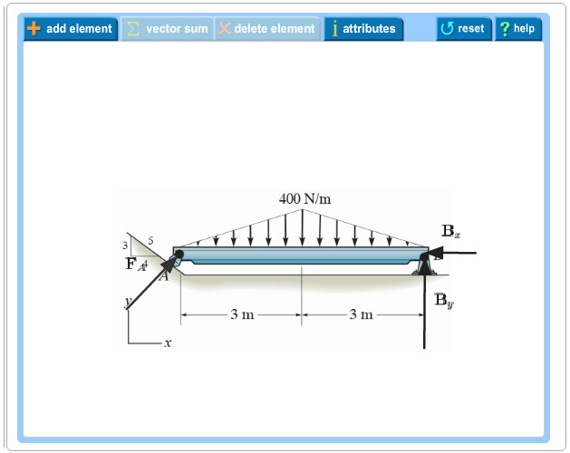
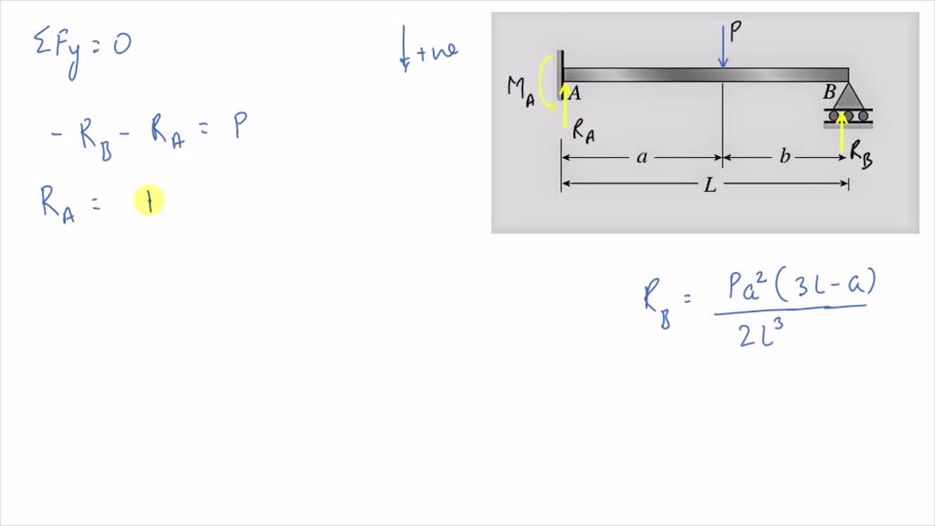
Free-Body Diagram of Beam:The beam is fixed at point A. Therefore, there are two reaction forces and one reaction moment at this point as shown below. We assume a direction for each reaction load. Also to simplify the calculations, the distributed force is represented by its resultant acting at its centroid.,
... is supported by a pin and a roller section of a beam : draw a free-body diagram that expose these forces and ❑The bending moment and shear force ...
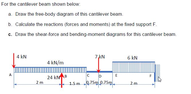
Solved for the cantilever beam shown below: a. draw the | chegg.com
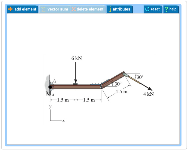
As a general rule, if a support prevents translation of a body in a given direction, ... Draw the free body diagram: R ... A cantilever beam is loaded as shown. Determine all reactions at support A. 5 kN/m 2 m 2 m 1 m A 20 kN 3 4 15 kNm EXAMPLE 3 .
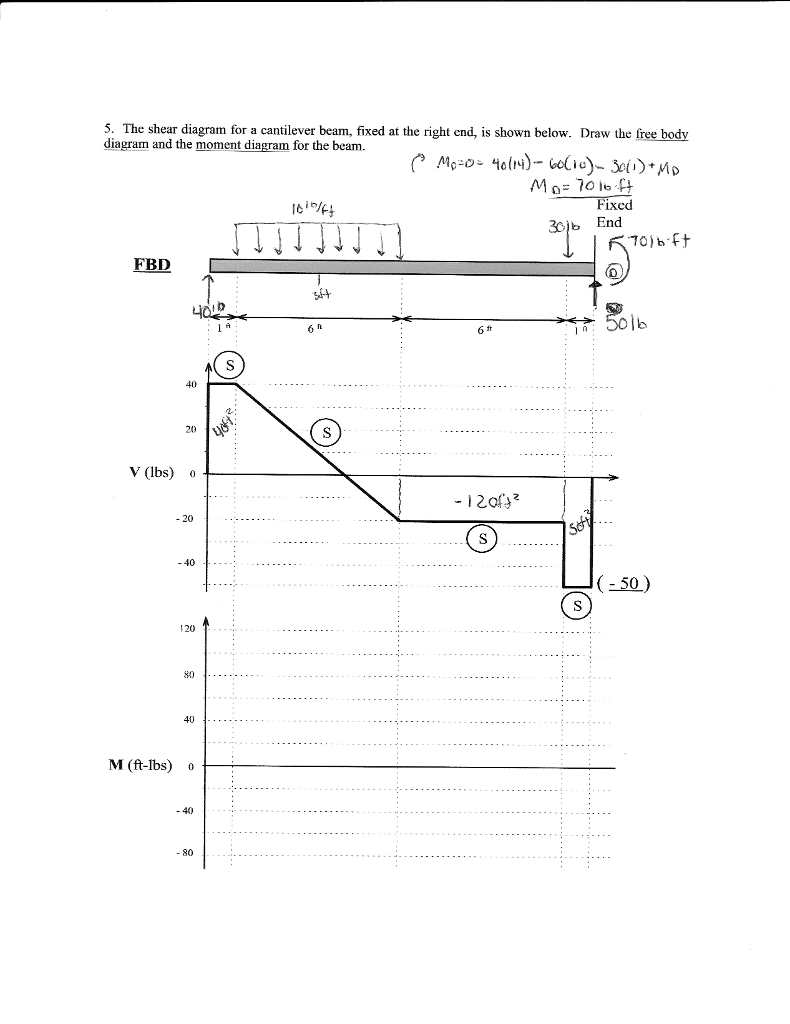
Solved 5. the shear diagram for a cantilever beam, fixed at ...
37 Free Body Diagrams Wednesday, October 3, 2012 New Support Conditions Pin Connection ! Another way Here is a pin support 38 Free Body Diagrams Wednesday, October 3, 2012 New Support Conditions Pin Connection ! On a pin, we know that there is an x and a y component of the reaction but without other

Draw shear force and bending moment diagram for cantilever beam ...
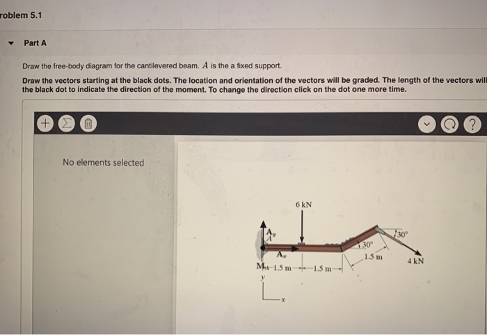
Part A Draw the free-body diagram for the cantilevered beam. Subject: Civil Engineering Price: 3.85 Bought 3. Share With. Part A Draw the free-body diagram for the cantilevered beam. A is the a fixed support. Draw the vectors starting at the black dots. The location and orientation of the vectors will be graded. The length of the vectors will ...
Shear force & bending moment diagram of cantilever beam | examples ...
The data anonymization approach is very efficient technique but if the scalability of the data set like private sensitive information is increased the ...
What are free body diagrams?
The bridge is built on the principle of the cantilever bridge , where a cantilever beam supports a light central girder, a principle that has been ...

Draw the moment diagram for the cantilevered beam. | study.com
Free body diagrams may not seem necessary in the relatively simple current applications, but as problems become more complex, their usefulness increases. The following is the process for determining the reaction at the wall for a cantilever beam.
Draw the free body diagram for the cantilevered beam a is the a ...
As the objective is to cause resonance in the waveguide trying to condense the energy at an antinode the length of the waveguide is dependent on the ...
Examples on equilibrium problem1 calculate the tension t
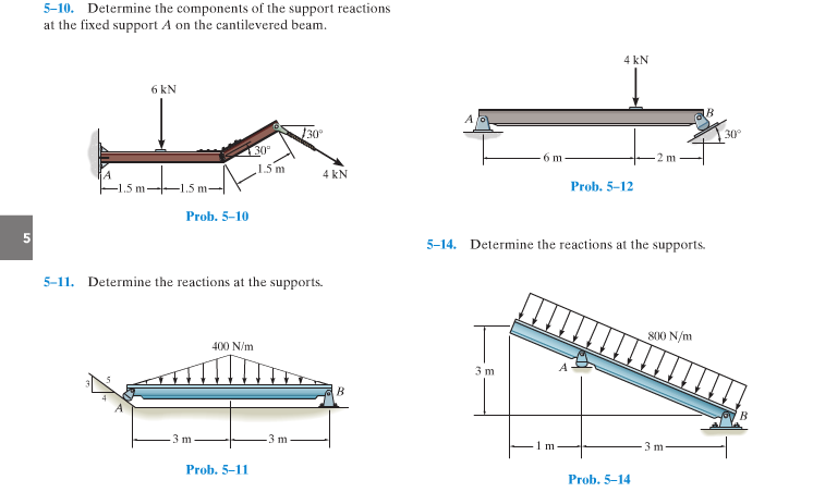
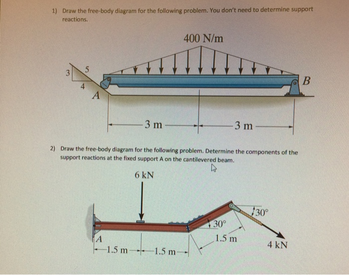
Draw the free-body diagram for the following problems. a) The cantilevered beam in Prob. 5-10. b) The beam in Prob. 5-11. c) The beam in Prob. 5-12. d) The beam in Prob. 5-14. 5-13. Determine the reactions at the supports All problem solutions must include an FBD. 5-10. Determine the components of the support reactions at the fixed support A on the
Ch4
Another way to describe a cantilever beam with uniformly distributed load (UDL) over it's whole length. (iii) A Cantilever beam loaded as shown below draw its S.F and B.M diagram In the region 0 < x <; a Following the same rule as followed previously, we get V =- P; and M = - P.x xx In the region a < x < L V =- P+P=0; and M = - P.x +P . xx x aPa
Solved problem 5.1 vectors: fa ,bx, by part a draw the | chegg.com
*7—56. Draw the shear and moment diagrams for the cantilevered beam. 300 1b - diagram of the beam's left through an arbitrary shown in fig. b will be to write the and mcnnent quations. The inœnsity the triangldar útributed load at of sectioning is — = 3333r Referring Fig. b , o V = {-300- 1b — +3001-0

Drawing shear and moment diagrams for beam
Draw the Free Body Diagrams. Learning Objectives 1. To be able to explain the equilibrium of Rigid Body Systems ... A Cantilever has to be fixed to support a load. Question 1. What is the difference between a Rigid Body and a Particle Question 2: Explain the Difference between a ... Beam Free Body Diagram. Actual Structure - A Truss Free Body ...

The overhanging beam is supported by a pin at a and the two-force ...
Stress Equations and Calculator for a Beam supported One End, One End, Cantilevered at Defined Location and Distributed Load Between Supports
Solved draw the free-body diagram for the cantilevered beam ...
roblem 5.1 Part A Draw the free-body diagram for the cantilevered beam. A is the a fixed support. Draw the vectors starting at the black dots. The location and orientation of the vectors will be graded. The length of the vectors will the black dot to indicate the direction of the moment.
Cantilever beams - moments and deflections
Solution: Show me the final answer↓. Our first step is to draw a free body diagram like so: Remember that since the beam is attached at a fixed support, a moment is also created at A. Let us now write an equilibrium equation for the x-axis forces. → + Σ F x = 0; \rightarrow^+ \Sigma F_x=0; →+ ΣF x. . = 0;
Solved:equilibrium of a rigid body | engineering mechanics ...
Draw the shearing force and bending moment diagrams for the cantilever beam subjected to the loads shown in Figure 4.6a. Fig. 4.6. Cantilever beam. Solution. Support reactions. The free-body diagram of the beam is shown in Figure 4.6b. First, compute the reactions at the support B. Applying the conditions of equilibrium suggests the following:

Cable supported beam example
Drawing a correct free-body diagram is the first and most important step in the process of solving an equilibrium problem. It is the basis for all the equilibrium equations you will write; if your free-body diagram is incorrect then your equations, analysis, and solutions will be wrong as well. ... Fixed support. The cantilevered beam is ...

Analisa struktur 4: apa yang dimaksud free body diagrams?
beam diagrams and formulas by waterman 55 1. simple beam-uniformly distributed load ... 22. cantilever beam-concentrated load at free end. 23. beam fixed at one end, free to deflect vertically but not rotate at other-concentrated load at deflected end 24. beam overhanging one support-uniformly distributed load. 25. beam overhanging one support ...
Solved problem 5.1 vectors: fa ,bx, by part a draw the | chegg.com
Expert Answer Transcribed image text: Draw the free-body diagram for the cantilevered beam. A is the a fixed support. Draw the vectors starting at the black dots. The location and orientation of the vectors will be graded. The length of the vectors will not be graded. Double-click on the back dot to indicate the direction of the moment.
Examples on equilibrium problem1 calculate the tension t
(which has an overhang) and a beam fixed (or restrained) at both ends, respectively. Cantilever beams and simple beams have two reactions (two forces or one force and a couple) and these reactions can be obtained from a free-body diagram of the beam by applying the equations of equilibrium. Such beams are said to be statically
Example 2
section of a beam : draw a free-body diagram that expose these forces and then compute the forces using equilibrium equations. The goal of the beam analysis -determine the shear force V and the bending moment M at every cross section of the beam. To derive the expressions for V and M in terms of the distance x measured along the beam.
Solved problem 5.1 vectors: fa ,bx, by part a draw the | chegg.com
... the case of cantilever shown in figure 5-1(a), there is no horizontal force and hence the fixed support will have only two reaction components (one ...
Solved determine the components of the support reactions at ...
Draw the free body diagram for the cantilevered beam a is the a ...
Solved) - draw the free-body diagram for the following problem ...

Solved) - draw the free-body diagram for the cantilevered beam. a ...
Determine the components of the support reactions - question solutions
Solved roblem 5.1 part a draw the free-body diagram for the ...
Dapatkah anda menggambar diagram gaya geser dan momen lentur balok ...

Determine the components of the support reactions at the fixed ...
Solved draw a free body diagram of the cantilevered beam | chegg.com

Shear force and bending moment diagram for cantilever beam with ...
A propped cantilever beam a b of length l carries a concentrated load p acting at the position shown

Determine the components of the support reactions at the fixed support a on the cantilevered beam

A cantilever beam ab is subjected to two concentrated load as ...
0 Response to "35 draw the free-body diagram for the cantilevered beam. a is the a fixed support."
Post a Comment