37 control 4 wiring diagram
Wiring Diagrams › GMC. If you run into an electrical problem with your GMC, you may want to take a moment and check a few things out for yourself. Before you dive in with a multi-meter, you will want to obtain a free wiring diagram for your specific model.You may need to locate a specific color wire and its exact location.
Wiring Code Identification Information WIRE CODE IDENTIFICATION Each wire shown in the diagrams contains a code (Fig. 1) which identifies the main circuit, part of the main circuit, gauge of wire, and color. The color is shown as a two-letter code, which can be identified by referring to the Wire Color Code Chart (Fig. 2).
Typical Controller Markings Typical Elementary Diagram IEC Typical Controller Markings Typical Elementary Diagram Table 4 Control and Power Connections for Across-the-Line Starters, 600 V or less (From NEMA standard ICS 2-321A.60) 1-Phase 2-Phase, 4-Wire 3-Phase Line Markings L1, L2 L1, L3: Phase 1 L2, L4: Phase 2 L1, L2, L3 Ground, when used

Control 4 wiring diagram
Basics 7 4.16 kV 3-Line Diagram : Basics 8 AOV Elementary & Block Diagram : Basics 9 4.16 kV Pump Schematic : Basics 10 480 V Pump Schematic : Basics 11 MOV Schematic (with Block included) Basics 12 12-/208 VAC Panel Diagram : Basics 13 Valve Limit Switch Legend : Basics 14 AOV Schematic (with Block included) Basics 15 Wiring (or Connection ...
Download Wiring Diagram STAG 400.4 DPI (model C1) 20.07.2020 Q-generation . Download STAG-300-6,8 QMAX PLUS Leads descripion Download STAG-300.8 QMAX PLUS wiring diagram Download STAG-300 QMAX BASIC leads description 17.05.2016 Download STAG-300 QMAX BASIC leads ...
Humbucker Wire Color Codes. Guitar humbucker wiring diagrams that show the coil winding start and finish wire colors, coil magnetic polarity and standard series in-phase humbucker wiring for the world's most popular guitar & bass humbuckers including: Anderson, Bare Knuckle, Bartolini, Benedetto, Bill Lawrence, Caparison, Carvin, DiMarzio ...
Control 4 wiring diagram.
1.0 Given a block diagram, print, or schematic, IDENTIFY the basic component symbols as presented in this module. ENABLING OBJECTIVES 1.1 IDENTIFY the symbols used on engineering electronic block diagrams, prints, and schematics, for the following components. a. Fixed resistor o. Fuse b. Variable resistor p. Plug c. Tapped resistor q. Headset d.
Wiring and Installation Guidelines, Edition 1.5 - v - Introduction Delta Controls has written Wiring and Installation Guidelines to provide its Partners with a primary source of recommended practices for wiring
12.2 Wiring Diagram Configurator 28 13. MX and QX Wiring Diagrams 29 14. Network Protocol Connections 34 14.1 Network Wiring — DDC-Modbus 34 14.2 Network Wiring — Foundation Fieldbus H1 36 14.3 Network Wiring — Profibus DP and PA 38 14.4 Network Wiring — DeviceNet 41 14.5 Network Wiring — HART 42
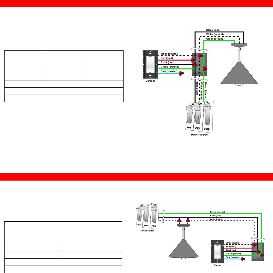
4-WAY CONFIGURATION WITH ESSENTIAL AUXILIARY KEYPADS This diagram shows a sample 4-way wiring configuration using an Essential Forward Phase Dimmer (C4-V-FPD120) or Switch (C4-V-SW120-277) with two Essential Auxiliary Keypads (C4-V-AUX). Daisy-chain each additional Auxiliary Keypad by extending the Ground, Traveler, and Neutral to each keypad.
C4-apd120-ll with 3 way wring? - general control4 discussion ...
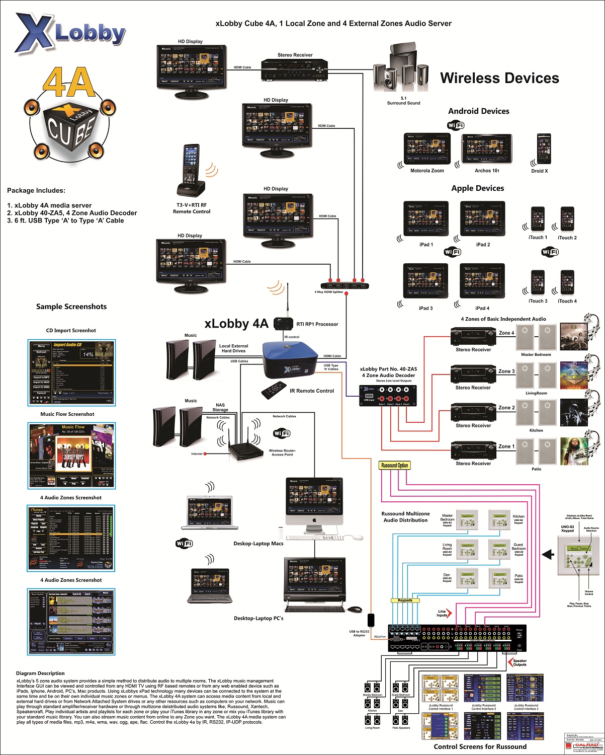
Xlobby news

Control4 with pir - general control4 discussion - c4forums | the ...

C4forums.com | largest public control4 community | powered by ...

Linear actuator wiring diagram generator | firgelli
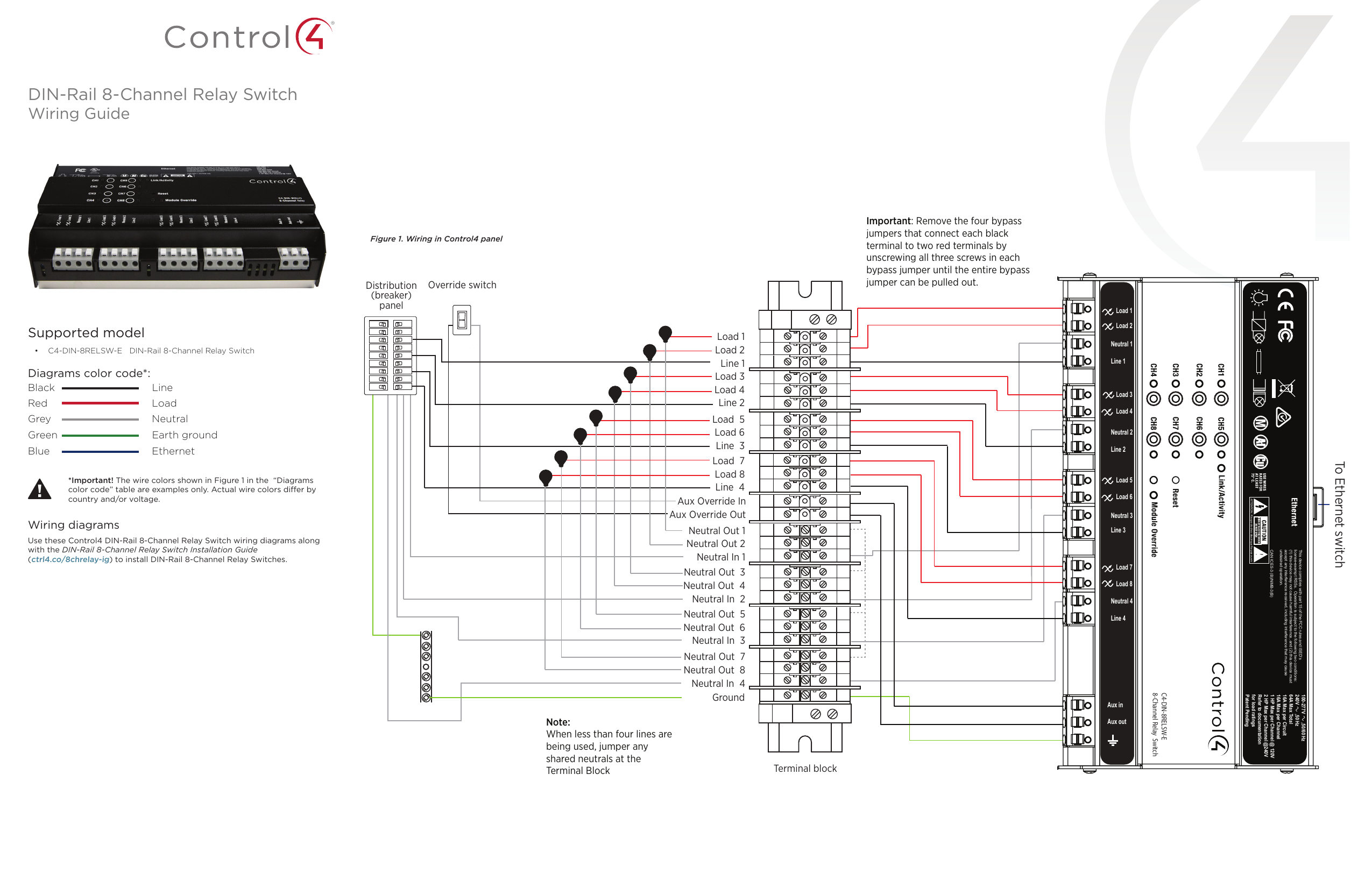
Control4 c4-din-8rel-e 8-channel relay guide | manualzz

Three-way switch to power half-hot outlet, keypad isn't working ...

Wiring diagram for a 4 gang light switch - electrical schematic ...

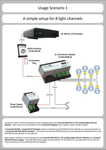
Installation of a control4 panelized lighting system

Control4 panelized lighting - wiring
Control4 ldz1011 ldz-101-x controllable dimmer user manual ...

Three way wiring - question & answer - c4forums | the control4 ...
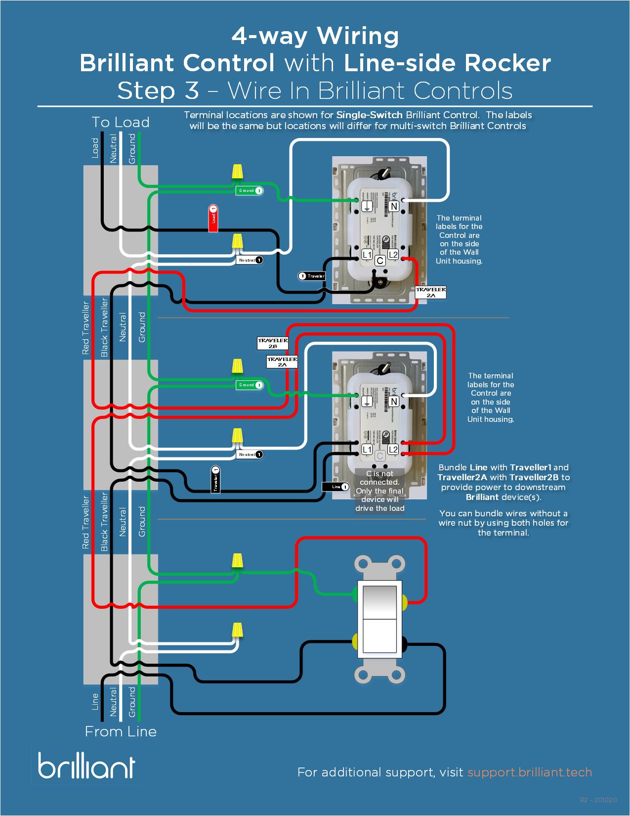
Brilliant control 4-way wiring guide – brilliant support

Guide to smart homes part 3 — intelligent installations

7 control4 ideas | home automation, control4, smart home

Detail control 4 switch wiring diagram wiring diagram and ...

Control4 dimmer lighting wireless light switch diagram pengkabelan ...
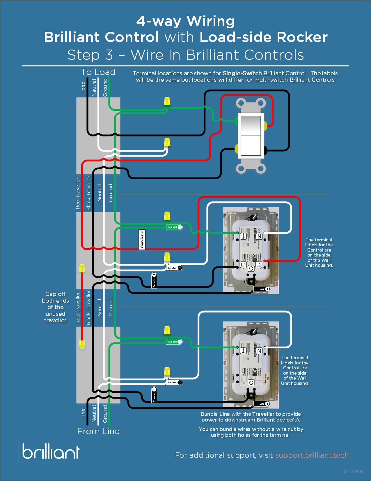
Brilliant control 4-way wiring guide – brilliant support
Control4/rs-232 serial pinout .3mb
Ldz1011 ldz-101-x controllable dimmer user manual wirelessdimmer ...

Someone tell me how to integrate this? - general control4 ...

Control 4 c4-sw1-z installation manual pdf download | manualslib

7 control4 ideas | home automation, control4, smart home
Getting started with control4 home automation documents
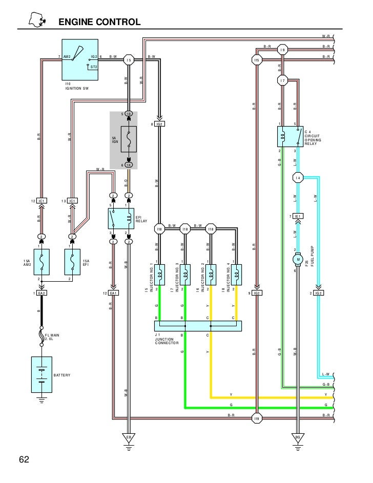
D.i.s wiring diagram

Smart home wiring guides

Terminalblockwiringguide_online | manualzz

C4apdkd adaptive phase dimmer/keypad dimmer user manual control4

Control4 c4-din-8tv-e 8-channel 0-10v dimmer guide | manualzz
Wiring diagram of the pump controller. | download scientific diagram
Visio-din rail - edit.vsd - control4

Wiring diagram to connect four capacitance sensors and a 5-v ...
C4dim1z wireless dimmer user manual 200 ...

Power turbine control system (n2) wiring diagram (continued)

01 – control4-sonos – singular motion

Wiring diagram electrical wires & cable schematic electronic ...
0 Response to "37 control 4 wiring diagram"
Post a Comment