37 shear force and bending moment diagram examples
Being able to draw shear force diagrams (SFD) and bending moment diagrams (BMD) is a critical skill for any student studying statics, mechanics of materials, or structural engineering. There is a long way and a quick way to do them.
Chapter-4 Bending Moment and Shear Force Diagram S K Mondal's Shear force: At a section a distance x from free end consider the forces to the left, then (V x) = - P (for all values of x) negative in sign i.e. the shear force to the left of the x-section are in downward
4.0 Building Shear and Moment Diagrams. In the last section we worked out how to evaluate the internal shear force and bending moment at a discrete location using imaginary cuts. But to draw a shear force and bending moment diagram, we need to know how these values change across the structure.
Shear force and bending moment diagram examples
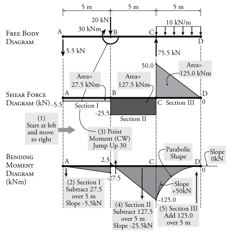
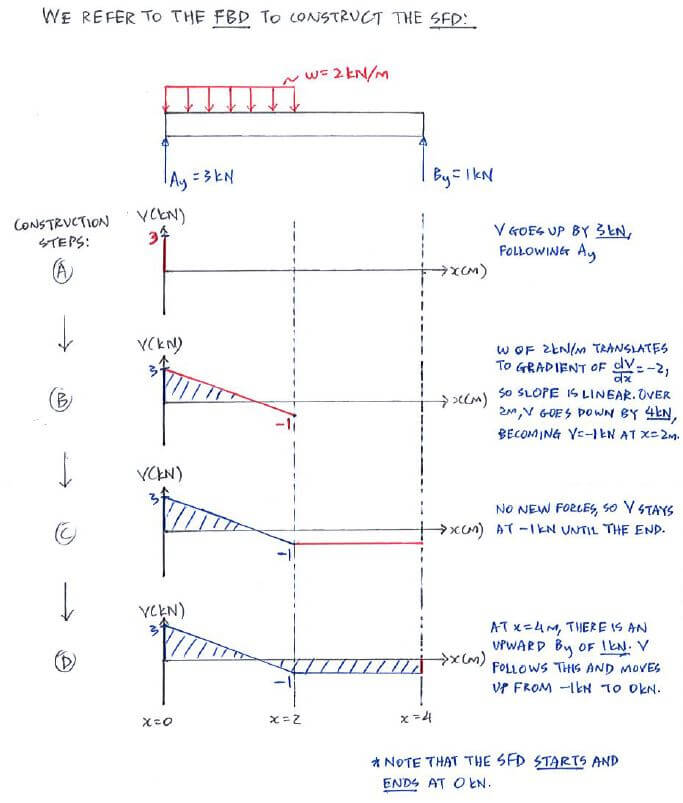
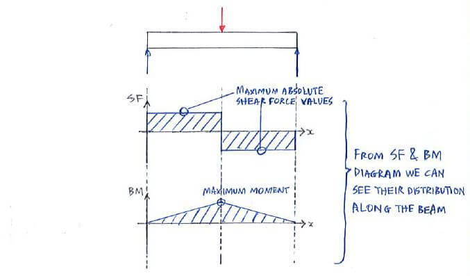
Shear Diagram. Moment Diagram. 1. Point loads cause a vertical jump in the shear diagram. The direction of the jump is the same as the sign of the point load. 2. Udl result in a straight, sloped line on the shear diagram. 3. The shear diagram is horizontal for distances along the beam with no applied load.
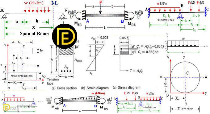
For the derivation of the relations among w, V, and M, consider a simply supported beam subjected to a uniformly distributed load throughout its length, as shown in the figure below.Let the shear force and bending moment at a section located at a distance of x from the left support be V and M, respectively, and at a section x + dx be V + dV and M + dM, respectively.
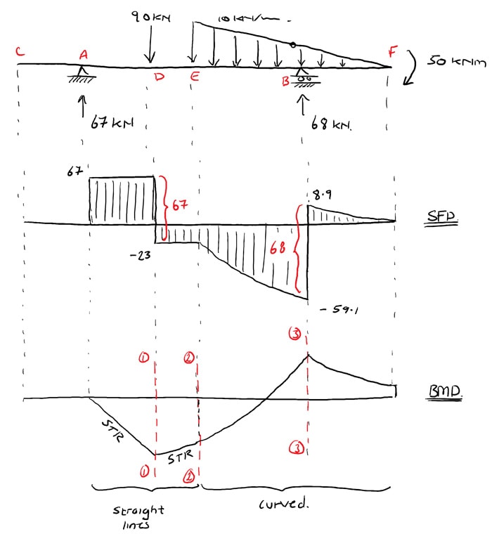
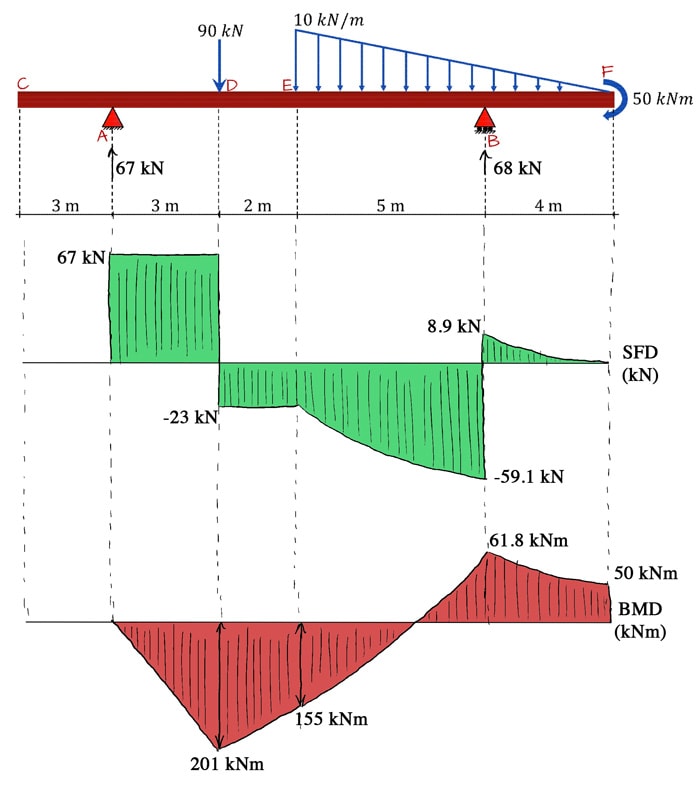
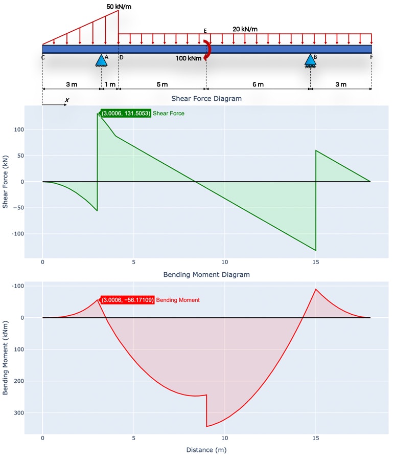
Shear and Bending Moment Diagram Example A beam is supported by a pin support at point A and extends over a roller support at point D. The beam is and subjected to a linearly varying load from A to B, a point moment at point D a point load at point E as shown. Draw the diagram and the bending moment diagram for the beam. Label
Shear force and bending moment diagram examples.
This engineering statics tutorial goes over an example of a simply supported beam with a single externally applied moment. In order to draw the shear force d...
Example 2. Simply supported beam calculation. Calculate the support reactions. Draw the Bending Moment diagram. Draw the Shear Force Diagram. Draw the Axial Force Diagram. More. Example 3. Cantilever beam calculation carrying a uniformly distributed load and a concentrated load.
Examples: Level 1: Single Point Load. This is example shows how to use the steps outlined in the "Steps" tab to draw shear force and bending moment diagrams. Level 2: Distributed Force. This example deals with a constant distributed force (shear is a linear function of x). Level 3: Point Moment. In this example, the point moment causes no shear ...
Shear and Moment Diagrams by Superposition Example: Draw the shear and moment diagrams for the following beam using superposition. 10 ft. A 5 k/ft. 10 k 10 ft. Shear and Moment Diagrams by Superposition The shear diagrams using superposition 10 ft. A 5 k/ft. 10 k 10 ft. 5 k/ft. + 10 k x V (k) 50 x V (k) 10 x V (k) 60 10 Shear and Moment ...
Let the shearing force at the section x be F and at .Similarly, the bending moment is M at x, and .If w is the mean rate of loading of the length , then the total load is , acting approximately (exactly if uniformly distributed) through the centre C.The element must be in equilibrium under the action of these forces and couples and the following equations can be obtained:-
Video created by Georgia Institute of Technology for the course "Applications in Engineering Mechanics". In this section students will learn about space trusses and will be introduced to shear force and bending moment diagrams.
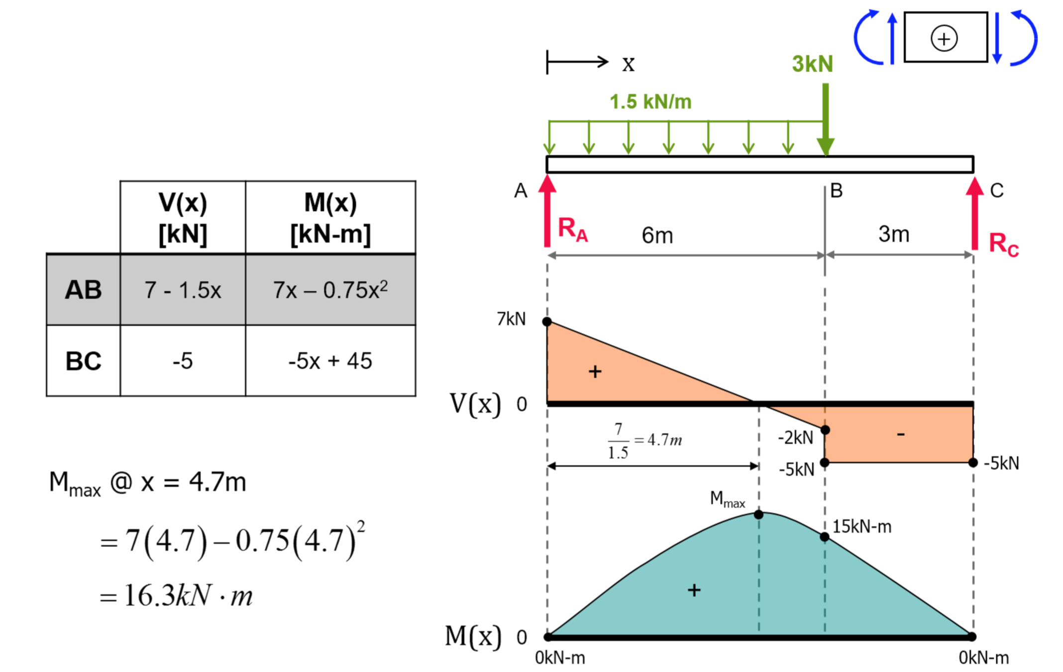
PDF_C8_b (Shear Forces and Bending Moments in Beams) Q6: A simply supported beam with a triangularly distributed downward load is shown in Fig. Calculate reaction; draw shear force diagram; find location of V=0; calculate maximum moment, and draw the moment diagram. 6k/ft 9 ft RA = (27k)(9-6)/9= 9k A B F = (0.5x6x9) = 27k x = (2/3)(9) = 6 ft
Shear and Moment Diagrams Consider a simple beam shown of length L that carries a uniform load of w (N/m) throughout its length and is held in equilibrium by reactions R1 and R2. Assume that the beam is cut at point C a distance of x from he left support and the portion of the beam to the right of C be removed. The portion removed must then be replaced by vertical shearing
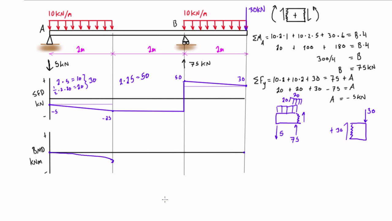
This engineering statics tutorial goes over an example of a simply supported beam with a mixture of point loads and distributed loads. In order to draw the s...
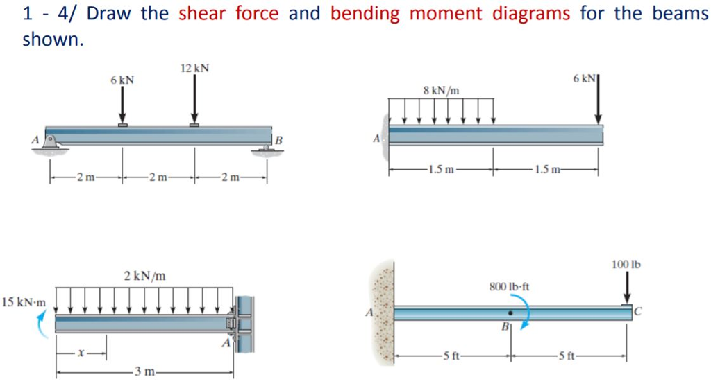
Calculate the shear force and bending moment for the beam subjected to the loads as shown in the figure, then draw the shear force diagram (SFD) and bending moment diagram (BMD). 3 kN/m 4 m A B EXAMPLE 8
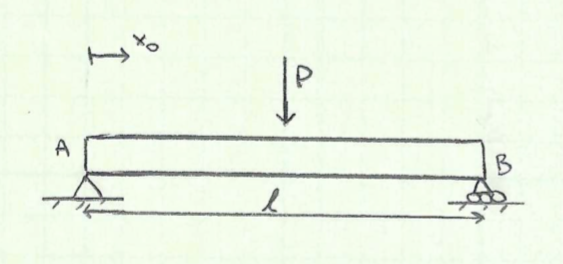
Example - Equation approach. ... Draw the shear force and bending moment diagrams for beam AB using the equation approach. Click below to show answer. X. Step 1: Draw FBD of beam and solve for reaction forces Step 1: Draw FBD of beam and solve for reaction forces ...
This engineering statics tutorial goes over another example of a simply supported beam, this time with multiple point loads. In order to draw the shear force...
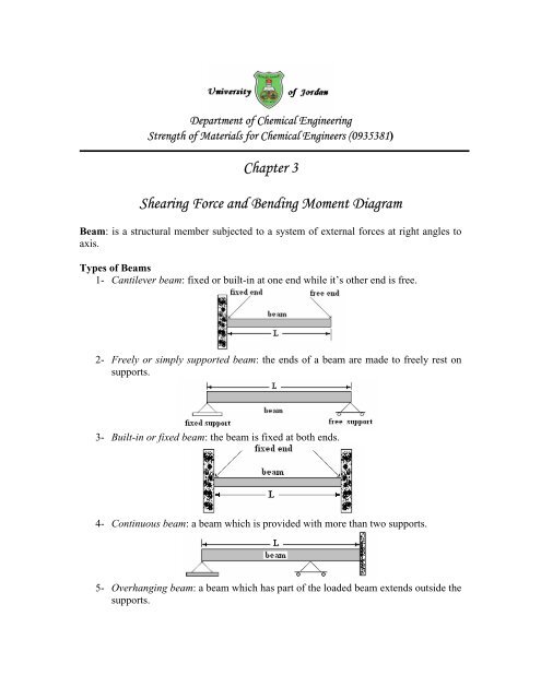
Chapter 3 shearing force and bending moment diagram - fet
Axial Force, Shear Force and Bending Moment Diagrams for Plane Frames Previous definitions developed for shear forces and bending moments are valid for both beam and frame structures. However, application of these definitions, developed for a horizontal beam, to a frame structure will require some adjustments.
Bending moment & shear force - structural analysis (aero 103)
This engineering statics tutorial goes over an example of a simply supported beam with a single point load. In order to draw the shear force diagram (SFD) an...
Shear force and bending moment diagrams sfd bmd
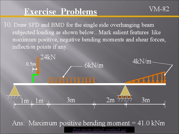
Shear force and bending moment diagram for overhanging beam

Solved example 3-2 derive the loading, shear-force, and | chegg.com

Mechanics ebook: shear/moment diagrams
Exercise: shear force & bending moment diagrams (solution) - tu ...

Shear force diagram - an overview | sciencedirect topics
Shear force and bending moment diagrams graphical method - slide share
Moment diagrams: examples
The ultimate guide to shear and moment diagrams | degreetutors.com
Solved draw the shear force diagrams and the bending moment ...
The ultimate guide to shear and moment diagrams | degreetutors.com

Drawing shear force, bending moment diagram
De-12: lesson 19. solved examples based on shear force and bending ...

Shear force and bending moment diagrams for uniformly distributed ...

Drawing bending moment diagrams effectively - mechanicalbase

Gate & ese - numerical problems on sfd(shear force diagram) and ...
Example - direct method | c5.3 shear force and bending moment ...

Shear force and bending moment diagrams | download scientific diagram

Bending moments and shearing forces in beams - ppt download

Draw shear force and bending moment diagram for cantilever beam ...

19 free body diagram ideas | teknik sipil, fisika, teknik

Shear force and bending moment diagram practice problem #2 ...

Ultimate guide to shear force and bending moment diagrams ...

Learn how to draw shear force and bending moment diagrams ...
Shear force and bending moment diagram practice problem #7
Theory | c5.3 shear force and bending moment diagrams | statics

Shear force and bending moment diagrams. | download scientific diagram
Chapter 4: internal forces in beams and frames” in “structural ...

Shear force and bending moment diagram and examples - pigso learning
How to draw shear force and bending moment diagram in case of ...
Shear force and bending moment diagram calculator | degreetutors.com

Shear force diagram and bending moment diagram - construction how

Shear force and bending moment diagram practice problem #2

Shear and moment diagram - wikipedia
0 Response to "37 shear force and bending moment diagram examples"
Post a Comment