40 led driver wiring diagram
Led Driver Wiring Diagram from portal.zanibonilighting.com. To properly read a wiring diagram, one offers to learn how the particular components within the program operate. For example , if a module will be powered up also it sends out a new signal of 50 percent the voltage in addition to the technician...
Applications of Mp3302 are LED back lights, LED based lighting gadgets etc. Functional block diagram of the MP3302 is shown below (Fig1). Circuit diagram of a fixed frequency LED driver using MP3302 led driver IC is shown in the diagram (Fig4) below. The circuit can drive a string of 10 white...
Led Driver Wiring Diagram - The basic principle behind the 230v led driver circuit is transformer less power supply. Crenshaw led lutron 3 wire led dimming wiring diagram lutron 3 wire led dimmer switch switched hot black electrical panel hot black 120v 277v ground ground dimmed hot orange led...

Led driver wiring diagram
led driver wiring diagram - What is a Wiring Diagram? A wiring diagram is a straightforward visual representation of the physical connections and physical layout associated with an electrical system or circuit. It shows the way the electrical wires are interconnected which enable it to also show where...
A wiring diagram is commonly made use of to repair issues and making certain that the connections have been made and also that every little thing exists. lifud led driver wiring diagram.
12v Led Driver Wiring Diagram - The Wiring. Install. Details: 230v Led Driver Circuit Diagram Working And Applications Circuit Diagram Led Drivers Details: on Wiring Diagram For 240v Led Downlights. Install 3 or 4 x V 3W LED downlights in all rooms. My thinking is to get it all installed and...
Led driver wiring diagram.
I’m a complete amateur and could use some advice if someone can spare the time for a few questions. Trying to build a temporary thing in advance of a Christmas event next week and am hoping to order my parts ASAP! ​ **Short version:** Q1: with LEDs, are ‘forward voltage’ and ‘operating voltage’ the same thing? Q2: are there any red flags in this online calculator’s suggested resistors or wiring diagram? https://ledcalculator.net/#p=9&v=4.5&c=50&n=6&o=w Q3: how lo...
led driver wiring diagram - A Newbie s Overview of Circuit Diagrams. A first look at a circuit diagram may be complicated, but if you can check out a subway map, you can check out schematics. The purpose is the exact same: obtaining from factor A to aim B. Literally, a circuit is the path that enables...
I'm working on a prop that uses multiple strips of Neopixel LED's controlled with an Adafruit Pro Trinket 5v 16mhz and powered by a 3.7v lipo battery plugged into a Powerboost 1000c. My problem starts shortly after I plug in the battery and the powerboost starts to heat up rapidly to the point it's too hot to touch. I am NOT at all experienced with these kinds of microcontrollers and am very new to arduino programming in general. I asked in r/ardunio earlier and the consensus was that the ...
**PART THREE HUNDRED AND THIRTY-SEVEN** ***((For those who would like to start from the beginning, Part One can be found*** [***HERE***](https://www.reddit.com/r/redditserials/comments/fs6i9s/bob_the_hobo_a_celestial_wars_spinoff_part_0001/?utm_source=share&utm_medium=web2x) ***))*** ***Monday*** “People will pay for quality, sir,” Angus remarked as he closed the door behind Boyd, having said very little on the drive down from the heart of the city (though that may have been because Boyd ...
Led Driver Wiring Diagram- wiring diagram is a simplified okay pictorial representation of an electrical circuit. It shows the components of the circuit as simplified shapes, and the knack and signal contacts in the midst of the devices.
Led Driver Wiring Diagram. Posted onApril 21, 2018May 26, 2018 AuthorZachary Long. We collect lots of pictures about Led Driver Wiring Diagram and finally we upload it on our website. Many good image inspirations on our internet are the most effective image selection for Led Driver Wiring...
Asked about DynaCup last week and a bunch of you suggested DIY. Thanks! EDIT: NOW WITH PARTS AND INSTRUCTIONS https://i.imgur.com/7k3BEfD.jpg I had been wary to dive into homebuilt for my first IH, but your suggestions made me take another look. I took the plunge, busted out the tools, spent a couple afternoons browsing discussions and plans, took an evening planning and building, an afternoon tuning, and it is good. Edit: Here’s how I made it. As always, this is not an endorsement, I am not ...
Wiring Diagram Led Driver - The image to the right shows an example. Led driver hot line black common neutral white yellow white black reverse phase elv wiring diagram line voltage 120v 120v output led load low voltage dc powered by ltf l t f l l c.
Connecting to live. Dimmable Led Driver Wiring Diagram. This Application Note "AN1 Ozone Wiring Diagram" provides technical information for the Ozone LED Driver has a wide voltage range input connector and a multifunction output Figure 2: LEDs, NTC, V / V Dimming, Vaux and.selection...
I'm looking for a wiring diagram for my 2009 LS Extended Cab. The purpose is to properly wire an exterior LED strip to the dome light from the driver side or passenger side connectors. This exterior dome light will act as a puddle light when the doors are open. My efforts to obtain a correct wiring diagram have not been successful.
I finally got my new Fysetc Spider v1.1 and Raspberry Pi 4 in and wired everything up according to this diagram ([https://github.com/FYSETC/FYSETC-SPIDER/blob/main/images/Spider\_v1.1\_wiring.jpg](https://github.com/FYSETC/FYSETC-SPIDER/blob/main/images/Spider_v1.1_wiring.jpg)). This is for an Ender 5 Plus converted to a coreXY. I did not mess with the potentiometers for the driver voltage as I understand the 2209's in UART do not require this. Then began setting up Klipper & Fluidd using ...
If LED is powered directly form a suitable power source, without an LED Driver circuit, in most cases Cables and Wires. LED/Optoelectronics. Connectors and Interconnect. As you can see in the LED driver circuit diagram, for a resistor value of 5.5 ohms the current drawn by the LED is limited to 0.23A.
230v led driver circuit diagram, working and applications ...
I have seen that people turn down the voltage going to the UV LEDs either by the PSU voltage screw or using a buck converter to stop getting cured resin in the vat after prints. I would like to do the same to stop my problem as well. But before I do I wanted to make sure my thinking is right for a possible solution. I have tried using the screw on the PSU to no success. It helped a good amount but not completely, so lowering the voltage clearly helps. But I’m not able to do it reliably at th...
Pe30da dali dimmable led driver 30w - buy dali dimmable led ...
Tridonic Led Driver Dimmable Wiring Diagram - Wiring Diagram. Drivers. Details: 10 Best For Tridonic Ballast Wiring Instructions Stephan Fuchs. Led Driver Compact Dimming Lc 27w 100 500ma 54v O4a Nf Sr Exc3 Excite Series.
Kit konversi inverter driver darurat,lampu panel led cadangan baterai - buy bertenaga baterai dipimpin cahaya panel,dipimpin cahaya panel baterai ...
Forward: Almost seven months ago, I posted a two part story to this sub titled “Apheraitors.” It caught a modest number of eyeballs, but those who read it seemed to react surprisingly positively to it. To be honest, I was flattered. And, high on the rush of having pleased and impressed so many strangers on the internet, I promised more to come. And truth be told I had more. This story was already half written and a few others were outlined when I made that promise. But, I faltered. Part of ...

88light - 12v driver wiring diagrams: 150w-600w
Hi, I do not know if this is the right place for this. I bought a Makerbase 2.1 board thinking it was a drop-in replacement for the Artillery sidewinder X1 board, but I am having multiple issues. I bought it with 2209 drivers. 1) I need the wiring diagram for the sidewinder X1 for this board. After tinkering hours on it, I lost the initial photos of the original boards layout. 2) The X axis is inverted and I cannot get it to work by switching the wires (as with most steppers). When I do switc...

Xi013c030v048dnm1 (929000719613) philips xitanium adjustable led driver 13w 300ma
Hi r/AskElectronics! I'm hoping someone can help me with this personal project of mine, as the title says, trying to convert an LG 19 inch LCD TV (19LG30-UA) to run off DC power, replacing the internal PSU with DC buck converters\*. *\*I know that I could just use an inverter to power the original PSU from a battery, but for various reasons I'm not interested in doing that, please don't suggest it\** I think I've gotten part of the way there, I've replaced the internal PSU's 15v and 5v output...
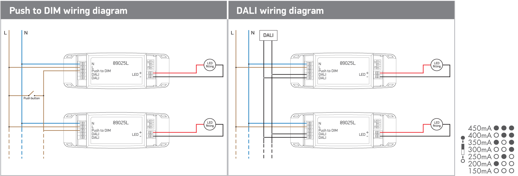
89025l | one light
Vlightdeco Trading Led Wiring Diagrams For 12v Led Lighting 2004 Jeep Grand Cherokee Driver Door Wiring Diagram Gallery Of Lifud Led Driver Wiring Diagram Sample

120vac kv series 30w constant voltage triac led driver - scpower
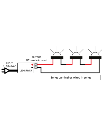
Collection of lifud led driver wiring diagram. Unsubscribe from led lucibel. The circuit is a constant current source which means that it keeps the led Crenshaw led 0 10v dimming wiring diagram 0 10v dimmer switch leviton ip710 lfz or equal for other types of dimming control systems consult controls...

24v 150w triac + push dim - dimmable led driver - single color
Make sure your driver does not exceed 1000ma when driving the xr e. Wiring leds in parallel. Simple Led Wiring Diagram Simp...

Lampu dim led dali 12v 24v dc 4ch 20a 240w 480w lampu strip ...
Hey, I'm using a transformer I've never used before on a commercial job. I have 347v lights on a switch but then some pot lights (4" lithonia Retrofit led with driver) which are 120v that need to be controlled by the same switch. So the ol supply house gave me a 347v to 120v transformer but no wiring diagram... I called and they didnt have one (they don't come in boxes). They called the supplier and they couldnt supply a wiring diagram... Weird I know. So it's gets weirder. Two black leads t...

Xi055c180v054bsj1 philips xitanium simpleset led driver - 55w 1050ma dimming
Led Driver Circuit Explained And Available Solutions. Schematic Diagram Of The Studied Led Driver Download Scientific. Lm3551 Lm3552 Led Driver Schematic Circuit Design Wiring. Resonant Mode Led Driver Electronic Circuit Diagram. Commercially Feasible Low Cost Led Driver Circuit 15 Watt.
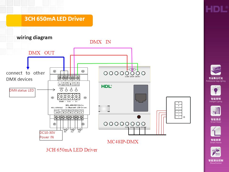
Dmx 3ch 650ma led driver wiring diagram dmx in dmx out - ppt ...
​ | \---------------------------------Table of Contents-------------------------------------| |:-| |[Chapter 24](https://www.reddit.com/r/The_Guardian_Temple/comments/r59mqv/of_nite_and_dei_book_2_chapter_24/) l [Chapter 25](https://www.reddit.com/r/libraryofshadows/comments/rahlnv/of_nite_and_dei_book_2_chapter_25/)| ​ Sellenia froze, looking around the dimly lit corridors painted red by the emergency lights. “*Soardoria?! What’s wrong?*” Sellenia called out in her min...

The power of dimming: control your strip lights
Led driver wiring diagram collections of dimmable led lights wiring diagram valid 12v led driver circuit. Constant current led driver circuit diagram unique 110v 220v 12v 0. A 0 10v dimmer is considered analog dimming and all usai 0 10v dimming options are considered to be sink type dimming.

Universal everline eld20unvl emergency led driver for ...
Name: led driver wiring diagram - Dimmable Led Lights Wiring Diagram Valid 12v Led Driver Circuit Diagram Inspirational Critical Systems. File Type: JPG. Source: doctorhub.co.
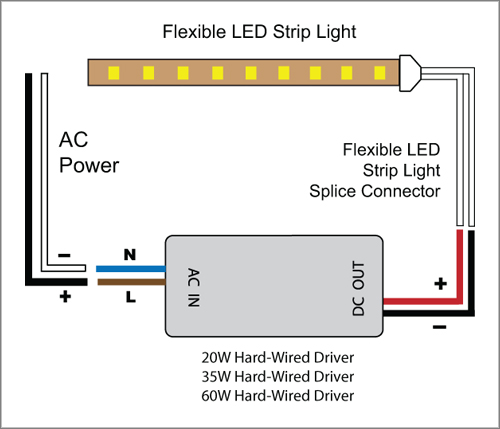
88light - 12v driver wiring diagrams: 20w-60w
Hello everyone, I hope some of you can help me out. I'm swapping leds and driver of my ancient tri-edc. Now, the original driver is electrically connected to the pill through a neat wire and a screw. Elegant way, but I gave a shot to simply solder the negative rim of the driver to the pill, you know, just where it sits (the canonical way, so to speak). Didn't really work, as soldering on the copper pill is beyond my skills. So yeah, I resort to the original solution, wiring the driver to the pil...

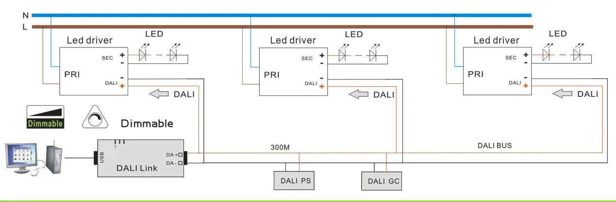
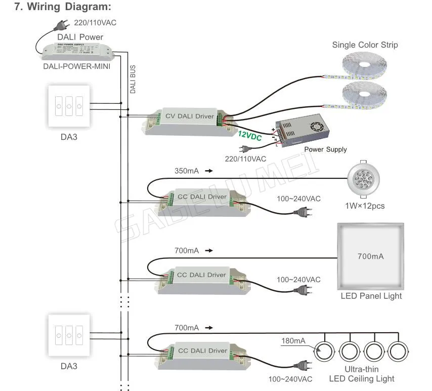
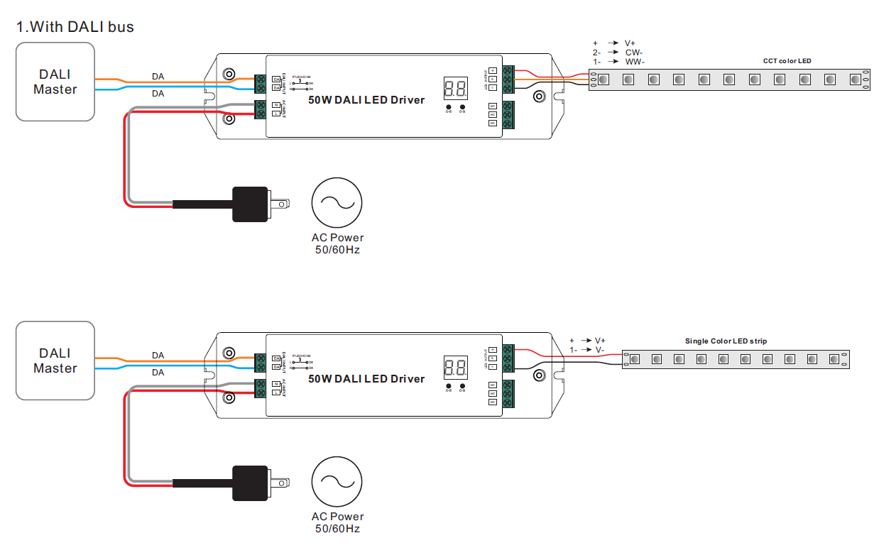
The wiring and installation details of dali dimmable led driver
Diagram d010 led driver wiring full version hd quality beefdiagram hotelrigelcatania it. Only qualified, licensed electricians should install. Wiring Diagram 4g63 4g63t Fantastic Electrical New 4G63. Pin on Denenecek projeler. 20 LED Emergency Light 회로도 Circuit projects, Emergency.
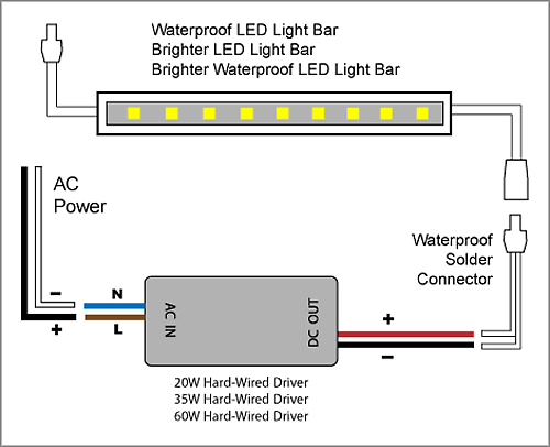
88light - 12v driver wiring diagrams: 20w-60w
I'm working on a prop that uses multiple strips of Neopixel LED's controlled with an Adafruit Pro Trinket 5v 16mhz and powered by a 3.7v lipo battery plugged into a Powerboost 1000c. My problem starts shortly after I plug in the battery and the powerboost starts to heat up rapidly to the point it's too hot to touch. I am NOT at all experienced with these kinds of microcontrollers and very new to arduino programming in general. [Here](https://imgur.com/WcUvLAb) is my wiring diagram and here is...
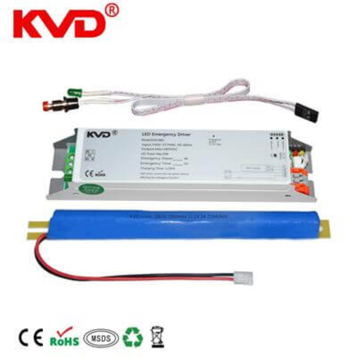
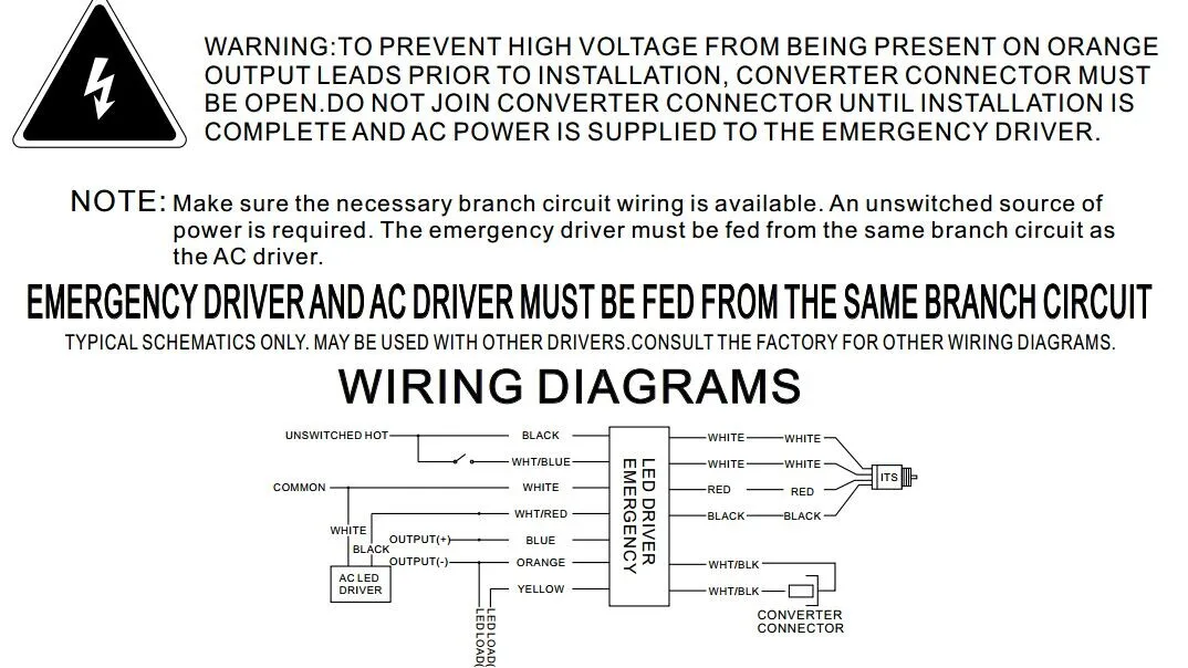
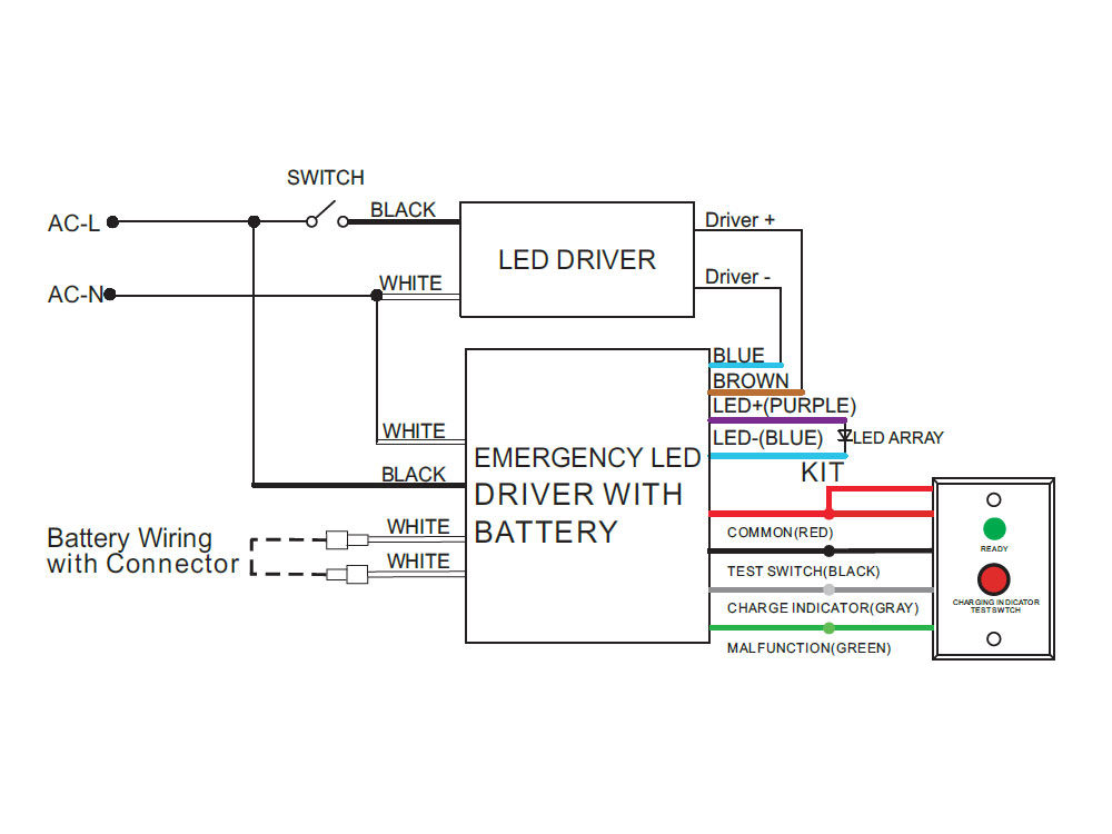
Led emergency driver wiring diagram
Rgb led driver the implementation of a rgb led fader using 555 timer and 4029 digital ic is the objective of this project.

120w 0/1-10v constant voltage dimmable led driver - scpower
Led Driver Wiring Diagram from portal.zanibonilighting.com. Print the electrical wiring diagram off in addition to use highlighters to trace the circuit. When you employ your finger or even follow the circuit along with your eyes, it's easy to mistrace the circuit. A single trick that I actually use is to printing the...

Advance xi075c200v054xpt1m $97.19 led driver, 27-54 v, 20-75 ...
Could someone explain to me what the difference between the ZEN72 and ZEN77 dimmers is? I'm trying to figure that out from the product pages but it's just not clicking with me. **Update with the response from Zooz:** The ZEN72 and ZEN77 are the new 700 series equivalents of the ZEN22 and ZEN27 500 series models. The differences for the ZEN72 and ZEN77 are similar to those of the ZEN22 and ZEN27, where they are wired differently in 3-way (or larger) installations and support different loads. H...

0-10 v kontrol pencahayaan diagram pengkabelan sirkuit dimmer ...
I just finished installing some rally type lights on my brush guard and figured I'd put together an install guide. The lights are a set of 4-wire LED 7 inch light pods from Amazon. You can find them by searching at Amazon for Audexen 7" LED Lights The lights have a High, Low, DRL, and Ground wire and I was able to connect it using two 3-way switches and two Relays. One of the 3-way switches handles the high beams and one handles the low beams. The up position on the 3-way switch provides power...
2 channels constant current dmx 50w dimmable led driver srp ...

Led drivers | diy led know-how | crescience

Led wiring guide - how to connect striplights, dimmers & controls
Gratis pengiriman dimmer dali led peredupan sopir 86mm sentuh ...

Fat-led-f1a led emergency pack connection wiring diagram ...
2 channels dali 50w dimmable constant voltage led driver srp ...

Ultimate guide: how to choose an led emergency battery backup kit
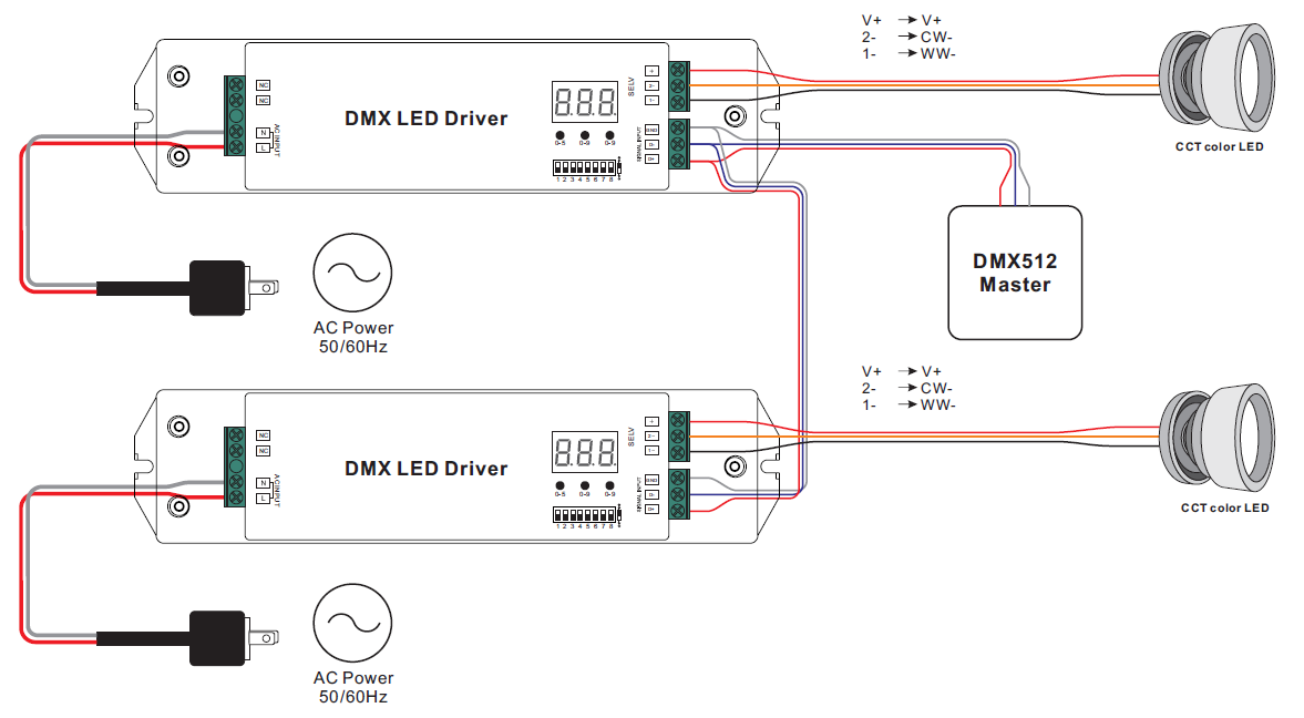
Dual channel led drivers for cct tuning - ltf technology

Led panels (1x4, 2x4, 2x2) and troffers installation guide ...

Philips xitanium led driver 50w sh 0.3-1a 62v 230v spot and ...

Vlightdeco trading (led): wiring diagrams for 12v led lighting

Magnitude lighting solidrive dimmable low voltage led driver ...

Zaniboni lighting : wiring diagrams part 1 : led lighting

Led driver dmx 36w 24v - dmx-36-24-f1p1

Led driver dmx 150w 12v - dmx-150-12-f1m1

Pin on gheenoe
Emergency led driver - 15 watts max - 25-48v output - 120-277v input
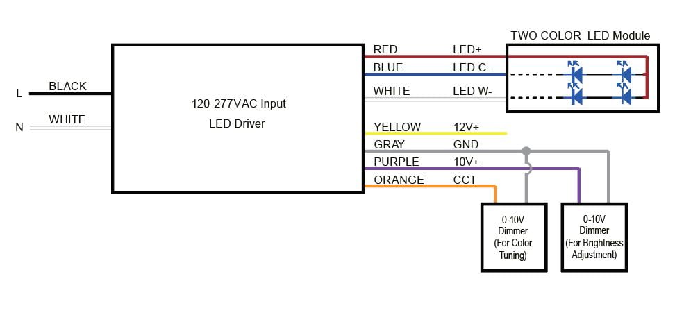
Dual channel led drivers for cct tuning - ltf technology
Installation | luxr led
0 Response to "40 led driver wiring diagram"
Post a Comment