41 accelerator pedal position sensor wiring diagram
If the "Accelerator Pedal Position [%]" is based on the Voltage output from the variable resistor, then when in Cruise the Voltage will be fixed at the idle Voltage except if the driver presses it down again. (In contrast, the "Throttle Opening Angle [%]" is probably the Throttle Position Sensor signal which corresponds to the throttle plate ...
ABS, Intelligent Cruise Control (ICC) Sensor, ICC Brake Hold Relay, Accelerator Pedal Actuator / Accelerator Pedal Position Sensor, Steering Angle Sensor, 55: 10: Washer Pump: 56: 30: Front Wiper Relay: 57: 15: Front Fog Lamp Relay: 58: 10: Daytime Running Light Relay: 59: 10: Tail/Park Lamps (Left Side) 60: 10
Joined: Jun 2016. RE: Throttle Position Sensor Problems - Solving them. I was taught that all wire repairs should be soldered with a linesman's knot and heat shrinked at a minimum, with adhesive heat shrink used on exterior connections. Butt connectors should be used just to get you from point A to B for a proper repair.

Accelerator pedal position sensor wiring diagram
Volvo XC70 2005 Fuse Box. Passenger compartment fuse box location: The fuse box A in the passenger compartment is located inside the access panel on the edge of the dashboard. The fuse box B is located behind the plastic cover below the steering wheel. Engine compartment fuse box location:
Additionally, the Cat C16 7CZ engine wiring diagrams are included in high resolution PDF format. This is a complete OEM reference for professional mechanics to service and repair the engine. ... Accelerator Pedal (Throttle) Position Sensor Circuit - Test Air Inlet Shutoff Circuit - Test ATA (SAE J1587 J1708) Data Link Circuit - Test ...
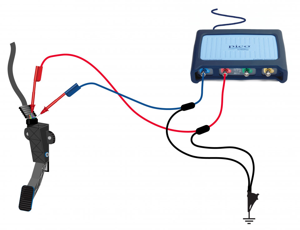
WHAT IS APP? · SENSOR LOCATION: · HOW TO TEST : · WIRING DIAGRAM : · WIRING TECHNICAL DATA: · TECHNICAL SPECIFICATION: · Accelerator Pedal Released Position Learning.
Accelerator pedal position sensor wiring diagram.
Fuse box location and diagrams: Opel / Vauxhall Meriva A (2009-2010) opel meriva 1.6 how to change coolant pump Free Auto Repair Manuals Online, No Joke Starting System \u0026 Wiring Diagram Cooling Fans \u0026 Wiring Diagram Accelerator Pedal Position Sensor Engine Fault.
Car not moving at all - Diagnostic Network. The magazine automotive repair shop owners and technicians read first to learn about the latest tools and equipment in the automotive aftermarket that can increase productivity in the shop and maximize billable hours. VehicleServicePros.com is the official website of PTEN magazine.
What Does the P0123 Code Imply? The P0123 code signifies an issue with the throttle/pedal place sensor. When the engine management module (ECM) detects that the throttle place sensor's output voltage ranking is exceeding the producer specification, it generates the P0123 bother code.The throttle place sensor is simply one other identify for a potentiometer and […]
Car Wiring Diagrams. PORTAL-DIAGNOSTOV Login/Sign up Login/Sign up
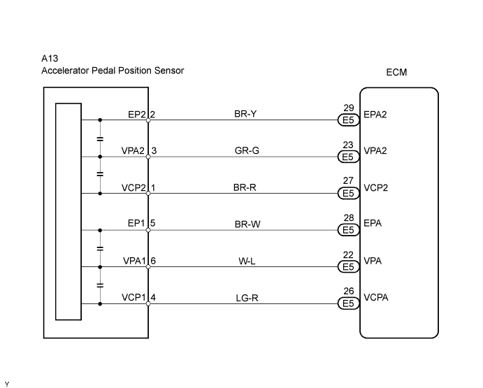
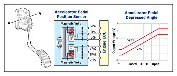
• An accelerator pedal position sensor is provided on the accelerator pedal. • A non-contact type throttle position sensor and accelerator pedal position sensor are used. VVT-i. Variable Valve Timing-intelligent (See page EG-48) Controls the intake camshaft to an optimal valve timing in accordance with the engine condition.
Throttle Position Sensor Adjustment 1 2010 Mitsubishi Triton 2.5 (5-spd manual) Start-Up and Full Vehicle Tour Tested: 2020 Mitsubishi Triton GLS auto How to install Leaf Helper SpringsStuck Open Fuel Injector (how to fix) Accelerator Pedal Position Sensor Power Window Wiring Diagram 1
6 Pin Accelerator Pedal Position Sensor Wiring Dia... Draw Wiring Diagrams - Software To Draw General Wi... Bush Plane Engine Diagram - What Materials Are Pla... Cherokee 1988 Electric Diagram : 1988 Jeep Wiring ... Panel Networking Admin Interface Guide / Network D... Emotional Intelligence Handouts - 1 /
39 diagram of a hurricane with labels. Sara Haynes Blackwood · 2015 · Education... type of natural disaster is most likely to occur ( hurricane , tornado, earthq… Written By Christine J. Bell. Sunday, December 5, 2021 Add Comment Edit. 39 baseball field diagram with positions.
fixed by replacing the wiring harness to the accelerator pedal position sensor (gas pedal) as… FORD - Car PDF Manual, Wiring Diagram & Fault Codes DTC Some FORD Car Owner's Manuals, Service Manuals PDF & Wiring Diagrams are above the page - Fiesta,
The new Dell OptiPlex 755 offers a compelling, versatile solution that can help you meet evolving business needs with the right technologies and services. Thanks to Dell 's innovative approach to scalable remote client management, the OptiPlex 755 offers you a choice between several systems-management options. Need Schematic Diagram for Desktop Dell Optiplex 755.
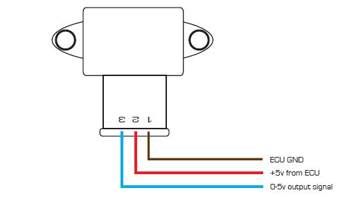
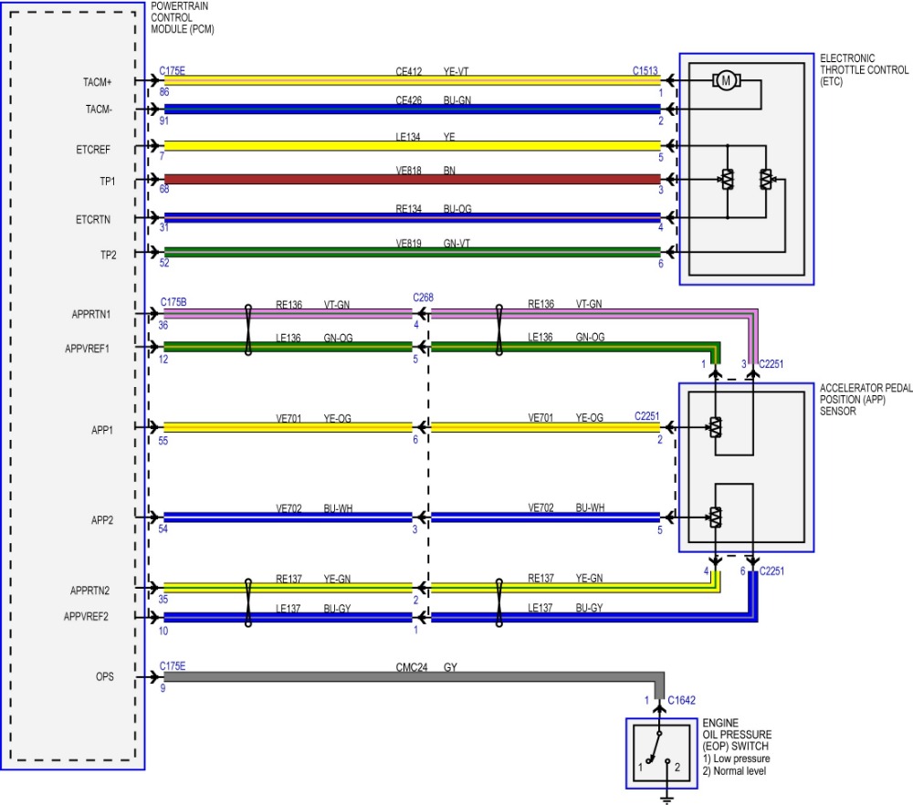
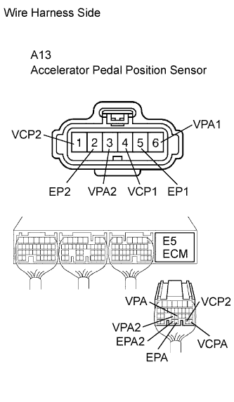
So, a 6 pin accelerator pedal position sensor wiring diagram is, two wires are for the earth, two for the input voltage, and two for signals back to the ...
Chrysler Cars & Trucks - P0001 dodge ram 3500 diesel - Chrysler Cars & Trucks- question about Cars & Trucks
P2138-accelerator pedal position sensor 1/2 correlation
A problem with the throttle actuator control system may cause the PCM to restrict its operations. This is known as the "limp home mode" or a "fail-safe" position, where the engine is held at idle or has limited power to prevent unwanted acceleration. Note: The definition of code P2111 may be different depending on the vehicle manufacturer.
Dbw pedal wiring questions - ls1tech - camaro and firebird forum ...
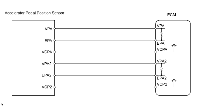
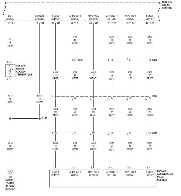
The electronic throttle control (ETC) system is a system that electrically opens the throttle valve. The parts of the ETC system, which consist of accelerator pedal position (APP) sensors, electronic throttle actuator, and throttle position (TP) sensors, are interconnected and controlled by a control module, which is usually the powertrain control module (PCM).
Throttle position sensors
Eautorepair.net redraws factory wiring diagrams in color and includes the component, splice and ground locations right in their diagrams. That saves a lot of time because you don't have to refer back to the component locator or circuit locations. Alldatadiy.com, on the other hand, uses the factory diagrams.
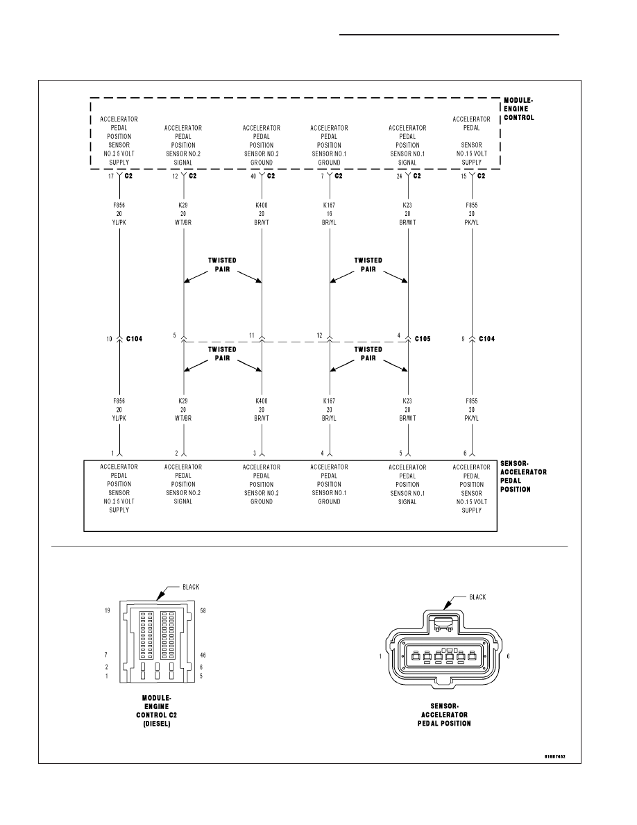
Chrysler 300/300 touring/300c, dodge magnum. manual - part 1417
I have Toyota Corolla 2.0D D-4D 2005. The engine does not respond to the accelerator pedal. It keeps running on idle rpm. The diagnostic tester (Texa Axone 2000) shows DTC P1120 - Accelerator Pedal Position Sensor Circuit Malfunction. I replaced the accelerator pedal with brand new one (original Toyota). However, this does not solve the problem.

Code no. p2122: accelerator pedal position sensor (main) low input ...
As an example Fig. 1 shows the wiring diagram of a STILL forklift accelerator pedal circuit which enables an electronic control unit (ECU) to measure the ...

Nissan almera tino v10. instruction - page 376
Cummins isx accelerator pedal position sensorCummins isx 15 code 1921 - dhcc.bcmt.pl Cummins isx accelerator pedal position sensor This is a image galleries about isx sensor locationyou can also find other images like wiring diagram parts diagram replacement parts electrical diagram
Throttle position sensor wiring diagram (1997, 1998 ford 4.6l, 5.4l)
1992 Cadillac Seville - Where is the obd connector on the 1992 seville- question about Cars & Trucks
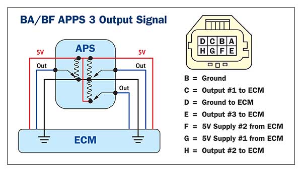
Accelerator pedal position sensors (apps)
Throttle Position Sensor. The MegaSquirt ® controller uses the throttle position sensor (TPS) to determine when the engine is at or near full throttle (to shut off feedback from the O2 sensor), when the engine throttle is opening or closing rapidly (and needing an accel/decel enrichment), and when the engine is flooded and needs to be cleared ...
Kia amanti questions - can anyone tell show me the wiring diagram ...
When the ignition SW is turned on and the brake pedal is pressed (Stop lamp SW on), if the stop light circuit is open, the current flowing from TERMINAL 7 of the light failure sensor to TERMINALS 1, 2 changes, so the light failure sensor detects the disconnection and the warning circuit of the light failure sensor is activated.
Accelerator pedal position sensor - analog
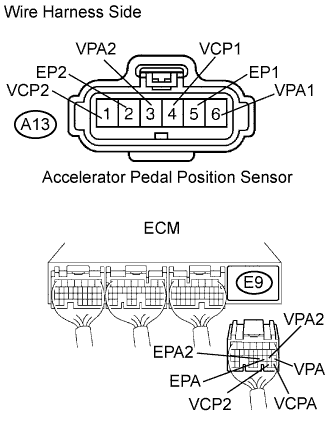
This is the repair procedure for the accelerator pedal position sensor. CIRCUIT DESCRIPTION ... WIRING DIAGRAM. INSPECTION PROCEDURE.5 pages
Gsic - global service information center
Car Speaker Wire Harness Diagram | Car Wiring Diagram. More information ... Part 1 -How to Test the Throttle Position Sensor (3.0L Mitsubishi Montero).

Automotives hub - app sensor wiring diagram | facebook
\u0026 Wiring Diagram CAM and CRK \u0026 Wiring Diagrams Accelerator Pedal Position Sensor O2 Sensor \u0026 Wiring Diagrams ECT Sensor \u0026 Wiring DiagramHow to test a fuel injector circuit with basic tools (open control wire) Where do I get wiring diagrams from? The answer is one click away...

Gsic - global service information center
Throttle control unit, engine management system (petrol) 10: F8: Accelerator Pedal Position Sensor, A / C Compressor Clutch Relay, Fuse / Relay Box Cooling Fan: 10: F9: Sound signal: 15: F10: Rear window washer pump motor: 10: F11: Engine Management, Glow Plugs Heating / Air Conditioning System Crankcase Ventilation Heater (Diesel) 20: F12 ...

Wiring diagram of a forklift accelerator pedal circuit. | download ...
The throttle position sensor measures the throttle plate angle as you step on and step off the accelerator pedal. Specifically, the throttle position sensor produces a voltage signal that increases as the throttle plate opens. When the throttle plate begins to close, the TPS voltage signal decreases.

Throttle position sensor wiring diagram. 08 int prostar isx ...
ABS, Intelligent Cruise Control (ICC) Sensor, ICC Brake Hold Relay, Accelerator Pedal Actuator / Accelerator Pedal Position Sensor, Steering Angle Sensor, 55: 10: Washer Pump: 56: 30: Front Wiper Relay: 57: 15: Front Fog Lamp Relay: 58: 10: Daytime Running Light Relay: 59: 10: Tail/Park Lamps (Left Side) 60: 10

Subaru legacy service manual - dtc p2123 throttle/pedal position ...
How to Test Crankshaft and Camshaft sensors 1 Accelerator Pedal Position Sensor How we rebuilt our Chevy Small-Block V-8 engine | Redline Rebuilds Explained - S1E2 How To: Remove\\Install A LS Oil Pump Install. (While Engine IS Still In Car.) ... V6 wiring diagram and connectors H002 11 VN Model (from Oct 1989) & VP Model V6 wiring diagram and ...
Drive by wire throttle wiring

Throttle by wire innova | roel on the blog
Circuit diagram

Throttle position sensor - toyota engine control systems

Nissan accelerator pedal position (app) sensor - erwin salarda
Gsic - global service information center
2015 f-150 - acceleration pedal position wiring diagram request ...
Megasqirt/efi tps wires. - passionford - ford focus, escort & rs ...
Hyundai elantra: throttle position sensor (tps). schematic ...
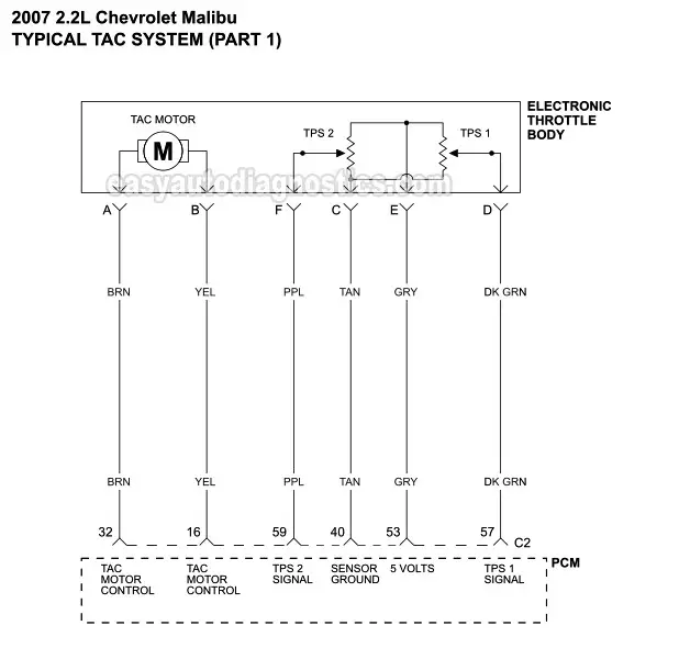
Tac system wiring diagram (2007-2009 2.2l chevy malibu)

Techdoc

Wiring diagram ecu 2kd-ftv | throttle | systems engineering ...
Hyundai accent: etc (electronic throttle control) system ...
Gsic - global service information center

Wiring diagram of a forklift accelerator pedal circuit. | download ...
Accelerator pedal position (app) sensor wiring diagram - anyone ...
Vz ls1 accelerator pedal position sensor | page 4 | just commodores
Gsic - global service information center

Throttle position sensor - toyota engine control systems in 2021 ...
Accelerator pedal position sensors (apps)

Pic request: throttle position sensor connector wiring | lexus is ...
Can't find the tps sensor on my 2005 | dodge cummins diesel forum

F super duty 7.3: need a wiring diagram for the accelerator

Infiniti g35 (v35). manual - part 430
0 Response to "41 accelerator pedal position sensor wiring diagram"
Post a Comment