38 5 wire regulator rectifier wiring diagram
A combination regulator / rectifier for. the 1979~1983 DOHC Honda 750~1100 can be found on my regulator / rectifier units page. All the rectifiers on this page are rated at is rated at 55 amps constant use. Most OEM 5. wire rectifiers are only rated at 18 to 22 amps. All the rectifiers on this page have 5 wires except where noted. Jun 03, · I need help wiring my five pin regulator/rectifier on the right side of the frame on my The wiring diagram shows the wires schematically and I need to know the color wire going from front to rear on the five pins that stick up. Regulator-Rectifier, 12 Volt Tympanium Corp.
The Best and Completed Full Edition of Diagram Database Website You Can Find in The Internet ... Go Wiring Diagram 24 Golf Cart Light Wiring Diagram 50cc Atv Wiring Diagram 12v Wire Diagram Benz B Class Wiring Diagram Jeep Wiring Diagram Multistrada 1000 Ds Wiring Diagram Ls Fuel Pump Wiring Diagram Activa I Wiring Diagram Bmw Wiring Diagram Air Bag Wire Diagram Control Unit Diagram For Toyota Corolla 1996 Ford Pickup Truck Wiring Diagram Reprint F 10f 25f 350 Way Light Wire Diagram Motor Wiring Diagram Ford Fairlane Wiring Diagram Vivo Y21 Sable Fuse Panel Diagram Signaling Adt Diagram Dev
5 wire regulator rectifier wiring diagram
The Best and Completed Full Edition of Diagram Database Website You Can Find in The Internet ... Accord Condenser Diagram Atv Stator Wiring Diagram Regulator Rectifier Wiring Diagram Gates Diagram With Truth Table Ford F 250 Fuse Box Diagram Impreza Fuse Box Diagram Mustang Coil Wiring Diagram Wire Diagram For An Elevator F 250 Lariat Fuse Box Diagram 6500e Generator Wiring Diagram E36 Central Locking Wiring Diagram A6010 Circuit Diagram Stratocaster Tbx Wiring Diagram 743 Altenator Wiring Diagram Paul 3 Way Switch Wiring Diagram Diagram 2005 Nissan Altima A C Pressure Ford Taurus Starting 5 Wire Regulator Rectifier Wiring Diagram from ae01.alicdn.com. To properly read a cabling diagram, one provides to know how the components inside the method operate. For instance , if a module is powered up and it also sends out the signal of fifty percent the voltage and the technician would not know this, he would think he offers a challenge ... Rectifier Regulator Wiring Diagram – 12v rectifier regulator wiring diagram, atv regulator rectifier wiring diagram, honda regulator rectifier wiring diagram, Every electric structure consists of various distinct components. Each part should be placed and linked to different parts in particular way. Otherwise, the arrangement will not work as it ought to be.
5 wire regulator rectifier wiring diagram. Understanding and Using Electronic Diagrams 5 In this simple power supply, all the voltage regulation functions are done by U 1, which is a 7812 positive voltage regulator. This is an integrated circuit that has regulation and protection cir-cuits built into one package. These circuits are easy to use, and are found in many applications. Sep 27, 2019 ... These instructions will cover all two wire regulator rectifiers we sell: (PodTronic, ... Early stators employ 6 poles and 3, 4 or 5 wires. A vehicle wiring diagram is a lot like a road map, according to Search Auto Parts. Wiring diagrams are laid out similar to a road map because the diagrams show how each major electrical system, individual circuit and sub-system connects, th... Jan 25, 2019 · The power supply section for the circuit is shown in Fig. 3. It consists of a step-down transformer (230V AC primary to 12V-0-12V, 1A secondary), bridge rectifier, filter network and regulator ICs 7812 and 7912 to provide +12V and –12V regulated DC outputs, respectively.
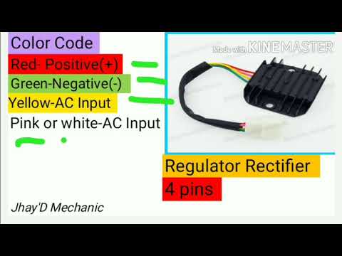
#2498 Get Free ACCESS ... HOME graphdiagrams.racingportuense.es need wiring diagram for 1997 gsxr 600 needs to have white suzuki gsxr 750 wiring diagram stator missing a wire - klr klx 600 650 l2 ignition switch wiring regulator rectifier promotion yamaha yzf r125 forum and owners club friendly bike Engine Diagram Animation Megane 2 Wiring Diagram Azure Diagram Icons S Socket Wiring Diagram Chevy Avalanche Wiring Diagram Ford 5 4 Expedition Engine Diagram Duo Therm Thermostat Wiring Diagram Infiniti G35 Wiring Harness Ga 17.02.2019 17.02.2019 7 Comments on Briggs And Stratton Voltage Regulator Wiring Diagram shunt is designed to read voltage drops due to the resistance of the metal be- tween the Two wires of the same color feeding a regulator/rectifier is a rectified . 5 pin regulator rectifiier wiring diagramSana makatulong po ito sainyo mga bro.Para sa iba pang vidio wag nyo pong kalimutan magSUBSCRIBELIKE AND SHARETO GOD... REGULATOR/RECTIFIER 7003-RR150 Tech Support: 360-687-4530 REGULATOR/RECTIFIER tech_support@trailtech.net WIRING GUIDE WIRING FOR SMALL BATTERIES UNDER 4 Ah: Trail Tech Regulator/Rectifier 7003-RR150 2 Yellow Wires: Red Wire: Blue Wire: Black Wire: Lighting leads. Connect to lighting leads from stator. Trail Tech stators have yellow lighting leads.
Buy Voltage Regulator 5 Wires 12V Rectifier Motorcycle Compatible with Dirt Bike ATV GY6 50 150cc Scooter Moped JCL NST TAOTAO: Rectifiers - Amazon.com ... The Best and Completed Full Edition of Diagram Database Website You Can Find in The Internet ... To Vga Wiring Diagram 460 Coil Wire Diagram Royce Phantom Workshop Wiring Diagram Sportster 1200 Wiring Diagram Golf 5 User Wiring Diagram Dot Diagram Of Fluorine Audio Wiring Diagram Club Car Solenoid Wiring Diagram Queen Vacuum Wiring Diagram Sierra 2002 2500 Fuse Paneldiagram Turbo Engine Diagram Toyota Rav4 Manual Transmission Diagram Corvette Wiring Diagrams Free To Usb Cable Diagram Wiring Diagram Diagram For A 50 Amp 120 Volt Rv Circuit Vn 750 Wiring Diagram 7 Pin Trailer Plug Wiring Diag Comes with an easy to read wiring diagram.. Included in kit: TWO mounting holes Magneto/Stator, Quad Wire Harness, Twin plug Cdi, Coil, NGK spark plug, Rectifier, Solinoid, Key switch, Estart/kill Cluster switch/remote Choke, Easy to read Wiring Diagram Atomik,Pitpro,Tdr,fit Hummer,Orion,Xmoto,Lei,Dmx,Tommahawk,Monsoon,Grudge... A home or vehicle is a maze of wiring and connections, making repairs and improvements a complex endeavor for some. Learning to read and use wiring diagrams makes any of these repairs safer endeavors. These simple visual representations all...
Lambretta 5 Pin Regulator Wiring Diagram
5 Pin Regulator Rectifier Wiring Diagram August 15, 2021. Puch Wiring Mopedwiki Motorcycle Wiring Puch Electrical Diagram . 110 Cc Atv Five Wire Cdi Diagram 110cc Chinese Quad Wiring Diagram Wiring Diagram Roy Evans 301 Moved Perm Motorcycle Wiring 150cc Scooter 150cc Go Kart . Atomic Dirt Bike 250 Wiring Diagram Wiring Diagram Amp Cable ...
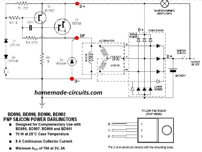
Motorcycle Rectifier Regulator Circuit Diagram - Wiring ...
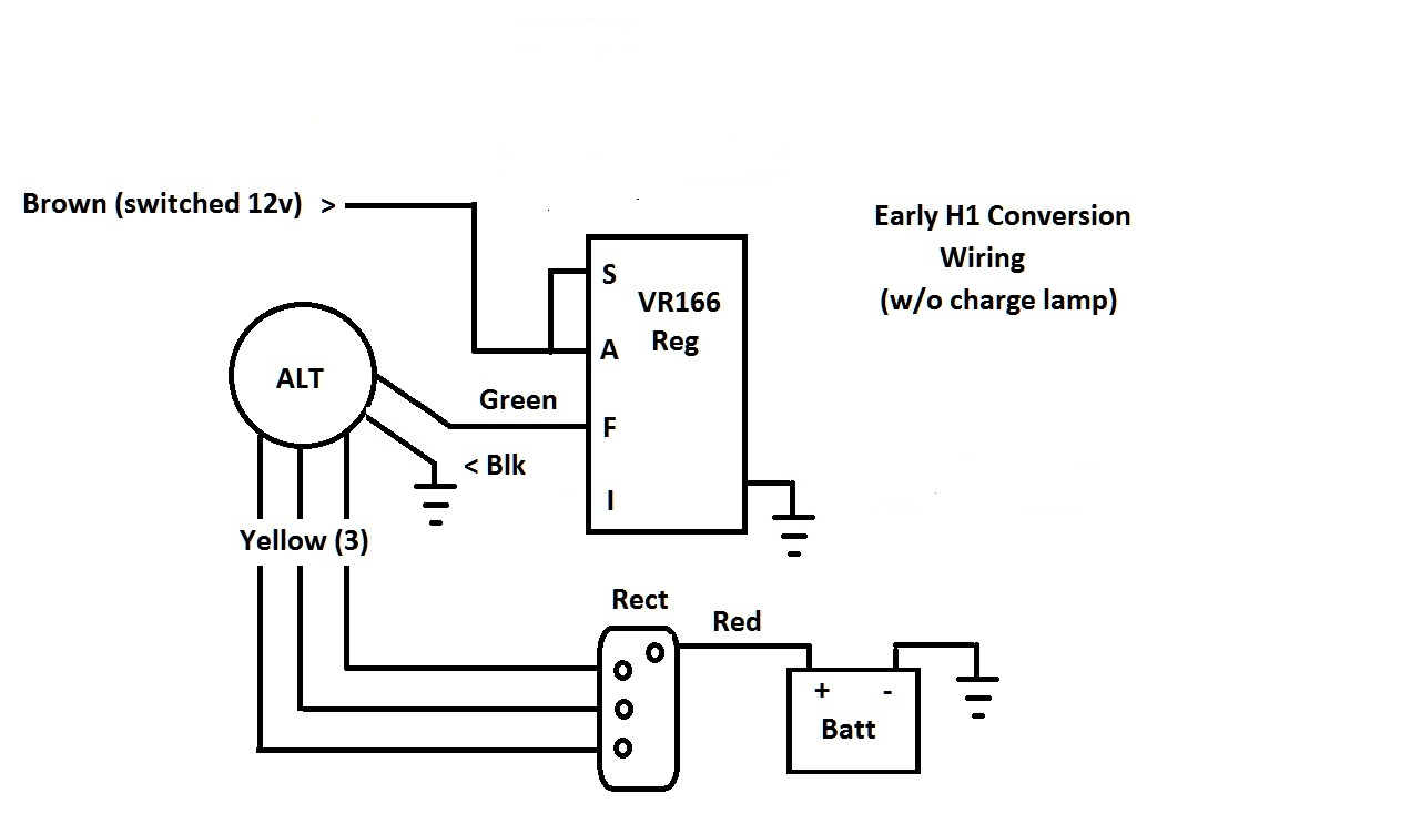
Mar 5, 2021 — Why would you need the regulator-rectifier to *also* be on the same ... The other four-wire regulators I've seen have two wires for AC input ...
BMW R45 with custom regulator charging problem | Adventure Rider
Lift off the old stator and label it with a marker as being "BAD". Replacing The 0 Voltage Regulator On Outboard Motors With A - Mercury Outboard Rectifier Wiring Diagram mercury outboard rectifier wiring diagram - You will want a comprehensive, expert, and easy to understand Wiring Diagram.

person holding red metal frame
The Best and Completed Full Edition of Diagram Database Website You Can Find in The Internet ... Pin 5 Wire Wiring Diagram Toyota Rav4 Wiring Diagram Manual Original Refrigerator Compressor Wiring Diagram 650 Fuse Diagram Piercing Diagram Test Ford 302 Engine Diagram Pc 150 Wiring Diagram Way Switch Wiring Diagram Fan Lightbo Sportage Blower Motor Wiring Diagram Gm Wiring Diagrams Gas Pump Wiring Diagram F150 Fuse Panel Diagram Yd22 Engine Wiring Diagram Accord Distributor Wiring Diagram Jeep Cherokee Alternator Wiring Diagram Ford F 150 Trailer Wiring Diagram 45 Cat6 Wiring Diagram Baseboa

Motorola Voltage Regulator Wiring Diagram | schematic and wiring diagram
The Best and Completed Full Edition of Diagram Database Website You Can Find in The Internet ... Ford F 15wiring Diagram Manual Original Voyager 2 5 Crd Wiring Diagram Wiring Diagram Hensim Ford F 150 4x4 Wire Diagram 2010 Gmc Sierra Wiring Diagram Automotive Wiring Diagram Symbols Ford Focus Wiring Diagram Chevy Cavalier Wiring Diagram Din A1 Turn Signal Flasher Diagram Legacy Radio Wiring Diagram 208v Wiring Diagram 325i Fuse Diagram Diagram For 2000 Chevy Impala Volvo S70 Fuse Diagram Diagram Instalasi Penerangan Maxima Wiring Diagram Original For 1997 Ford F 150 Fuse Box Diagram Wiring

5 Pin Regulator Rectifier Wiring Diagram : Regulator Ducati w silniku lotniczym Simonini ...
Aug 05, 1991 · It breaks down the color-codes used with most of our bikes (the one exception is described in a footnote) and even tells you where each wire begins and ends. The August Full Cycle release, "How to Read Honda Wiring Diagrams", will refer you to this chart so please keep it around as d reference.

5 Pin Regulator Rectifier Wiring Diagram : 4 Pin Voltage Regulator Wiring Diagram Hobbiesxstyle ...
The Best and Completed Full Edition of Diagram Database Website You Can Find in The Internet ... Voice Diagram Her 1302 Electrical Wiring Diagram Delta Auto Trans Wiring Diagram Datasheet Wiring Diagram 205 Gti Wiring Diagram Rectifier Wiring Diagram Intrepid Fuse Box Diagram 2 9 Engine Diagram Ford F800 Wiring Diagram F350 Fuse Diagram Nova Ss Wiring Diagram Further Camaro Console 777 Diagram Chevy S10 Wiring Diagram Auto Zone Volt Dc Limit Switch Wiring Diagram Ford Edge Fuse Diagram Manual F350 2015 Fuse Diagrams Mustang Gt Fuse Box Diagram Cruiser Radio Wiring Diagram Impala Convertible

5 Wire Rectifier Wiring Diagram : Amazon Com Rectifier 4 Wires Voltage Regulator Replacement For ...
Your regulator has to match the stator you have. You either have the wrong regulator or a bad one. If you don't have a 5 wire hook-up, try going with a 4 pin reg. Put the Yellow and white diagonal from each other and the green and red diagonal from each other on the other 2 pins. Dave @ Absolutely Scooters.

6 Wire Regulator Rectifier Wiring Diagram : Msl 068 Single Phase Regulator Rectifier Wiring ...
Online 5 wires 12v voltage motorcycle regulator rectifier tester a for wiring atv gy6 50 150cc scooter 4 fit 6 wire universal 12 volt dc chinese motorcycles 3 phase suzuki 32800 30b01 pins diagram. As stated earlier the lines at a Rectifier Regulator Wiring Diagram signifies wires.

Gy6 Rectifier Wiring Diagram - MORPHINE-AND-DRUGS
Universal Parts 12 Volt 6 Amp YTX7A-BS Battery - Maintenance Free Dry AGM 12, , 5 pin Regulator for cc and cc GY6 engines commonly found Universal Parts Complete Wiring Harness for cc and cc 4-stroke GY6. rectifier/regulator go along with the other items running on the electrical system; stator common on most 50cc scooter but also can be found ...

BATTERY SOLUTIONS: Modification Rectifiers Regulator Motorcycle
5 pin electrical regulator rectifier wire harness connector 5P250-312 Description Aftermarket 6.3/7.8mm female rectifier/regulator connector socket. It is regulator rectifier wire harness connector with 15 cm wire length Wire Size: 0.3-1.30 mm², Crimp or .....

6 Pin Regulator Rectifier Wiring Diagram - How To Test ...
Aug 27, 2017 ... I have not ordered it yet but would love to order the correct part ONCE. Any help would be greatly appreciated! Wiring diagrams for the ...

Voltage Regulator 4 Pin Regulator Rectifier Wiring Diagram ...
I have a 5 wire reg/rec 3 yellow go to stator , red wire goes to the starter relay, black/white wire was originally wired as a ground.
Wiring Diagram Regulator Rectifier - SAMIHAH88
Full wave regulator schematic, motorcycle regulator, hid charging, regulator diagram, hid conversion, 5 wire regulator, rr schematic, . Luckily, there are some places that may have just what you need. 5 pin regulator rectifiier wiring diagram sana makatulong po ito sainyo mga bro. Para sa iba pang vidio wag nyo pong kalimutan mag subscribe .
yellow blue and black coated wires
This section is shared between all Wiring Diagrams for continuity. 11) Connector face views are shown with pin and circuit numbers and wire colors and circuit... Header/Footer Information Page layout Page Orientation: All Wiring Diagrams will be 8.5" x 11", landscape. Margins: For detailed measurements for margins, headers...

5 Wire Regulator Rectifier Wiring Diagram
#969 Get Free ACCESS ... 2000 suzuki marauder wiring diagram wiring schematic wiring diagram for custom motorcycles category suzuki wiring diagram nejdou prav u00e1 sm u011brov u00e1 sv u011btla motork u00e1 u0159sk u00e9 f u00f3rum 2001 suzuki intruder 800 wiring diagrams yhc 055 motorcycle voltage regulator rectifier motorbike fender marauder wiring diagram 1999 suzuki intruder 1500 manual john deere d105 wiring diagram mtd 11a b13m229 manual mtd 11a b13m229 manual 2009 suzuki boulevard m50 service manual pdf mtd 11a

brown and white concrete buildings during daytime
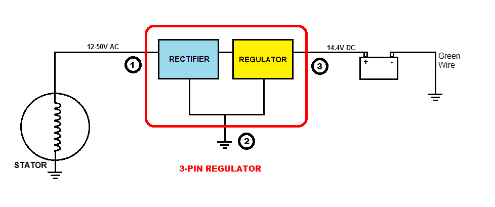
Recitifer Regulator Signal Wires. Many Rick's Motorsport Electrics Rectifier/Regulators eliminate what is commonly referred to as a "signal wire" on OE pieces. For example, on a 1981 Kawasaki KZ440, there are 5 wires going to the OE part: 2 yellow wires (AC inputs), white/red (DC "+" output), black/yellow (DC "-" output), and a ...

man in blue jacket and blue denim jeans standing on brown rock formation during daytime
Apr 26, 2020 - Motorcycle Regulator Diagram and Amazon: Wires V Voltage Regulator Rectifier - 18+ Motorcycle Regulator Diagram .Motorcycle Regulator Diagram ...
5 Pin Regulator Rectifier Wiring Diagram : 4 Pin Voltage Regulator Wiring Diagram Hobbiesxstyle ...
Normally, the pins for USB1 and USB2 are in seperate rows. Diagram 2: Simply plug the connector onto the 5-pins row, and make sure that the pin assignments and wire assignments are matched correctly. Diagram 3: Alternatively, you can plug the connector onto the 4-pins row, and leave the S-GND wire unconnected.

4 Pin Rectifier Wiring Diagram - Wiring Diagram
Jul 1, 2016 ... CAUTION. Installation of electrical devices can be hazardous. Connecting wires incorrectly can result in severe damage. Always.
Aftermarket Honda Regulator Rectifier | OEM Style Honda Replacement Part
panel where the rectifier are open, causing high "ripple" or A/C voltage (while charging volts and amps are still. I replaced the voltage regulator (aftermarket, not Polaris), and I thou Polaris had a 3-wire regulator-rectifier that was used on sleds with electric start. Studying the wiring diagram a bit more, I can see that elec start sleds.
How To Test A Regulator/rectifier - Youtube - Rectifier ...
Jan 17, 2022 · Some HONDA Motorcycle Manuals PDF & Wiring Diagrams are above the page.. Japanese brand Honda is known as one of the largest motorcycle manufacturers.. In 1961, Honda sold a record number of motorcycles to the industry - 100,000 a month. Production starts in Taiwan, and an official representative office opens in Germany. A year later, in Belgium, the …
Rectifier Regulator Wiring Diagram - Wiring Diagram
Yamaha outboard rectifier wiring diagram. You need a lighting coil to supply an ac current that the rectifier will convert to a dc. Adding a regulator rectifier to an outboard motor so you can charge a battery is a relatively simple job. Sample motorcycle wiring diagram included in this shipment and dictionary of automotive terms a teacherweb.

6 Wire Rectifier Wiring Diagram - Wiring Diagram Networks
The Best and Completed Full Edition of Diagram Database Website You Can Find in The Internet ... Yamaha Yzf R6 Wiring Diagram Alternator Wiring Diagram 2wire Chevrolet Trailblazer Radio Wiring Diagram Tank Wiring Diagram Chevy 1500 Stereo Wiring Diagram Drill Wiring Diagram Free Picture Schematic Generator Stator Wiring Diagram Chevy Blazer Wiring Diagram Wiring Diagram Whirlpool Ed5shax Ignition Wiring Diagram Engine Wiring Diagram Free Picture Schematic Diagram International 9400 Diagram 3g Nissan Sentra Wiring Diagram Mercedes Wiring Diagram Dirt Bike Engine Diagram Diagram Fiat Strada 2

Gy6 5 Wire Rectifier Wiring Diagram : Rectifier Voltage Regulator 5 Pin Gy6 Shopee Philippines ...
Aug 04, 2021 · 2 phase 5 wire motorcycle regulator rectifier wiring diagram pdf. We ve even included standard wire colours where appropriate. Lamberts bikes motorcycle part wiring diagrams. Simply plug the connector onto the 5 pins row and make sure that the pin assignments and wire assignments are matched correctly. M 3 2 2 2 phase 5 wire. I have a 5 wire rectifier on my swapped gy6 ruckus i know exactly where 4 of the wires go green ground red battery.

20+ 4 Wire Rectifier Wiring Diagram Pics - Switch
Aug 28, 2021 · Vacuum Diagram As Well 2001 Ford F 150 5 4 Vacuum Line Diagrams On size. 5 pin rectifier wiring diagram. On the solder side of. Reddit gives you the best of the internet in one place. Design a regulated DC power supply of 5V which can be used to run a LED using AC voltage as the input.

Gy6 5 Wire Rectifier Wiring Diagram - WIRGRAM
Single Phase Half Wave Controlled Rectifier with 'R' load: As shown in figure below primary of transformer is connected to ac mains supply with which SCR becomes forward bias in positive half cycle. T1 is triggered at an angle α, T1 conducts and voltage is applied across R.

Tympanium Electronic Voltage Regulator-rectifier 332-104/a Wiring Diagram
Replacing The $100 Voltage Regulator On Outboard Motors With A $4 - Mercury Outboard Rectifier Wiring Diagram. The diagram offers visual representation of the electrical structure. However, this diagram is a simplified version of this arrangement. This makes the procedure for assembling circuit simpler. This diagram provides advice of circuit ...

Yamaha Rectifier Wiring - Wiring Diagram Schemas
5 Pin Rectifier Wiring Diagram - wiring diagram is a simplified agreeable pictorial representation of an electrical circuit. It shows the components of the circuit as simplified shapes, and the faculty and signal contacts amongst the devices. A wiring diagram usually gives instruction nearly the relative approach and treaty of devices and ...
5 Wire Regulator Rectifier Wiring Diagram For Your Needs
Auto parts accessories 4 wire full motorcycle regulator rectifier tester voltage wiring harley a for mosfet kawasaki 6 universal 12 volt units atv gy6 50 150cc scooter wires 5 2 phase pma install too high 3 and rectifiers wave black motored pins flwd suzuki 32800 30b01 12v lucas regulators diagram pin with. 6 volt solid state regulator rectifier.
4 Pin Rectifier Wiring Diagram - Wiring Diagram
Read the Wiring Diagram : Study the diagram to understand how the circuit is supposed to work. Read the detailed description added in complex diagrams. 3. Find the Problem : Use the Troubleshooting section with each circuit. 4. Make the Repair. 5. Test the Repair: Operate the repaired system in all modes to be sure the whole problem is fixed ...
Gy6 Rectifier Wiring Diagram - MORPHINE-AND-DRUGS
Trying to find the right automotive wiring diagram for your system can be quite a daunting task if you don’t know where to look. Luckily, there are some places that may have just what you need. Here’s where to start. Before you search for a...

My Photo Gallery - regulator_rectifier_wiring_diagram
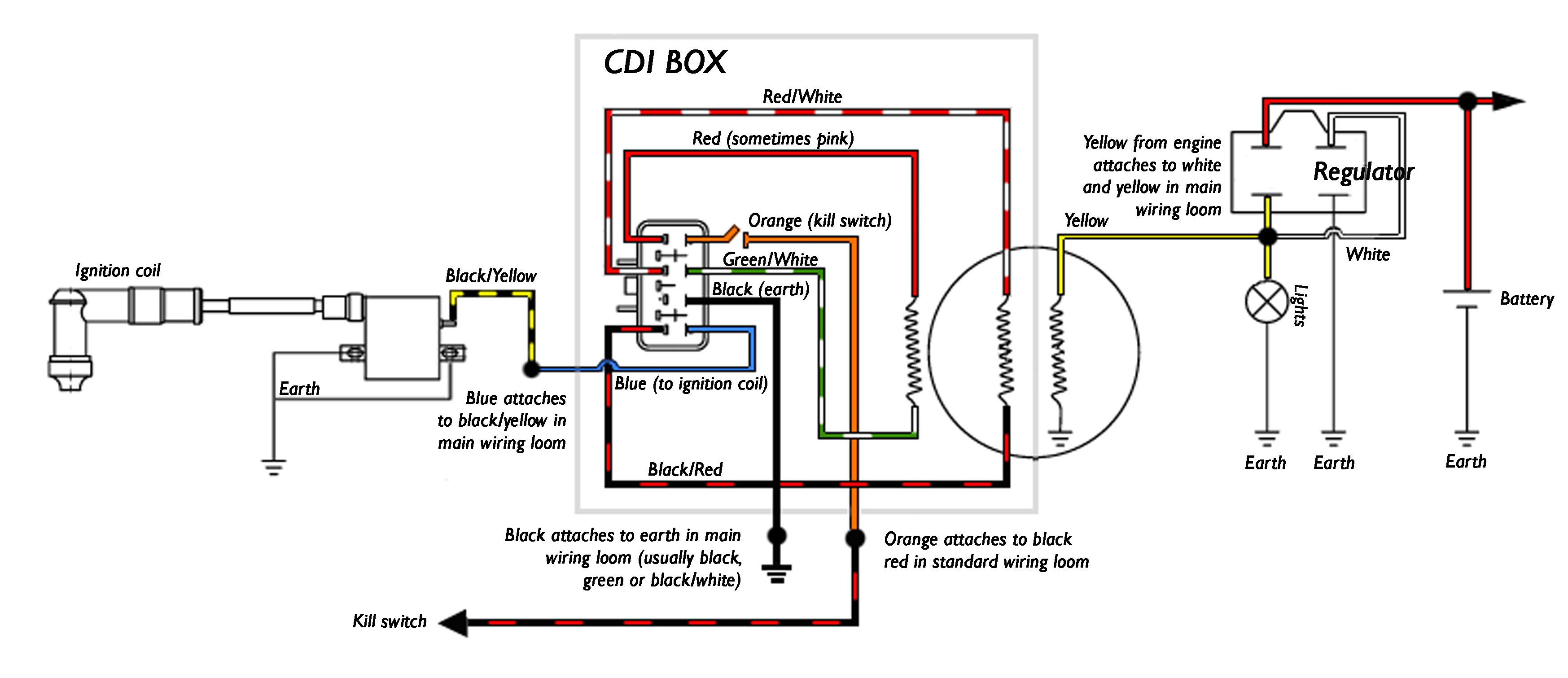
Oct 02, 2021 · Wiring diagram for voltage regulator. However this diagram is a simplified version of this arrangement. Here is a wiring diagram of the typical 5-wire CDI system on a lot of scooters comprising pick-up input battery 12 volts in Gnd and Ignition coil out pins. Marvellous Motorcycle Regulator Rectifier Wiring Diagram Ideas size.

Wiring new rectifier to Indiana 650. 6 wires stock, can I use 5 wire rectifier? - Ducati.ms ...
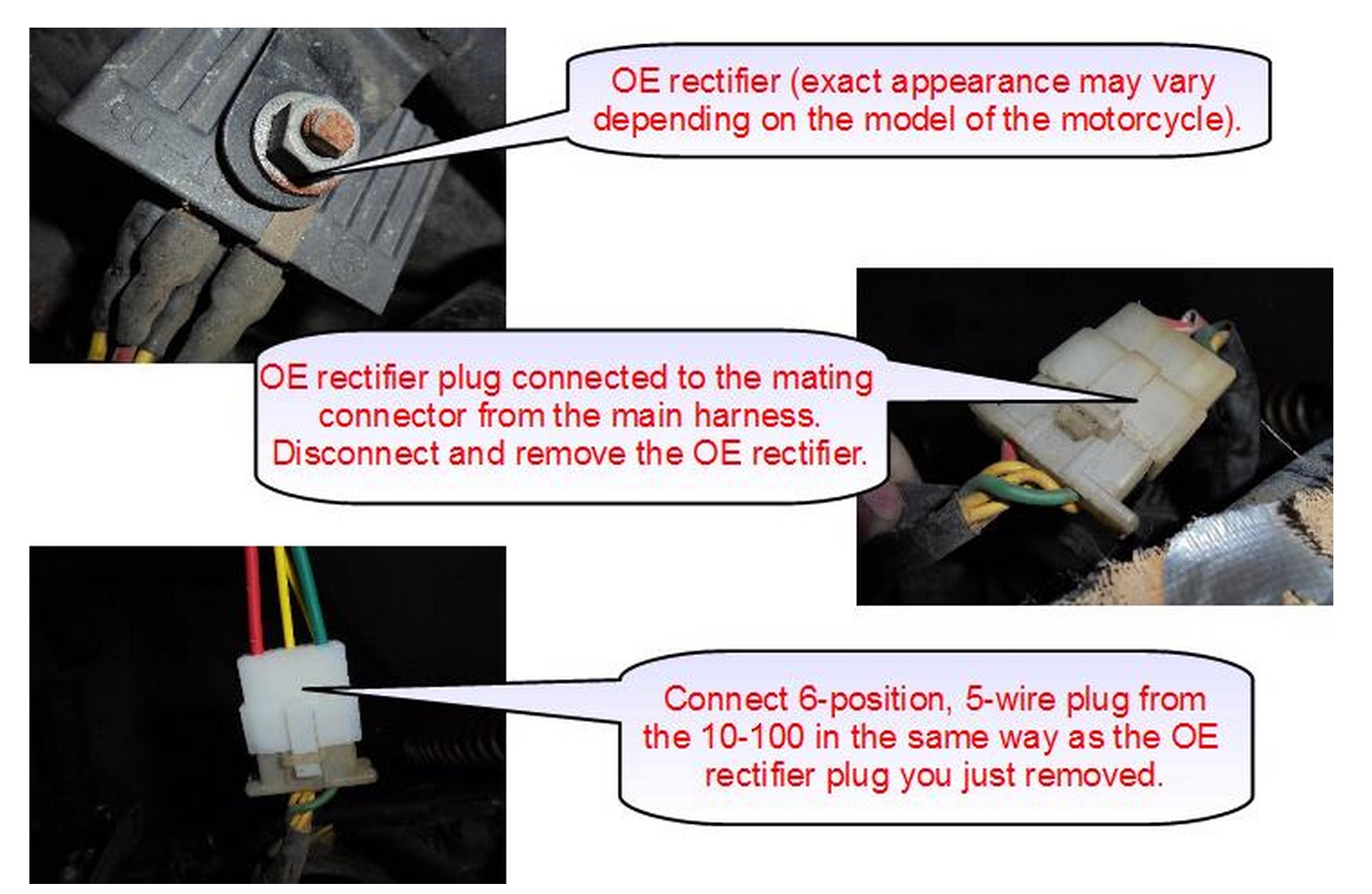
Connecting the rectifier - Disconnect the 6-position, 5 wire connector from the OE rectifier & plug the identical connector on the 10-100 in its place. Excerpted from a CB750/550 Wiring Diagram The 10-100 regulator is connected to the harncss via the 3 single wires with spade terminals (these plug into the wires that originally were going to ...

person holding black iphone 5
How to wire a gy6 scooter regulator rectifier and how it all works part 3 the regulator duration. The article was submitted by mr. The color code remains the same. Regulator rectifier diagram here you are at our site this is images about regulator rectifier diagram posted by maria nieto in wiring category on may 08 2019.

Gy6 5 Wire Rectifier Wiring Diagram : 12 12v Rectifier Regulator Diagram Motorcycle Motorcycle ...
4 wire / 5 wire regulator rectifier wiring diagram and Explain Regulator (TAGALOG). Watch later. Share. Copy link.

6 Pin Regulator Rectifier Wiring Diagram : Three Phase Fitting Instructions / Please insert the ...
The Best and Completed Full Edition of Diagram Database Website You Can Find in The Internet ... Single Coil 5 Way Switch Wiring Diagram Taurus Fuse Box Diagram Ford 7 3 Powerstroke Wiring Diagram Micra 2015 Wiring Diagram Wire Trailer Wiring Diagram Backup Lights Ford Ranger Stereo Wiring Diagram Pro Car Wiring Diagram Kia Sorento Wiring Diagram Ford Escape Starter Wiring Diagram Diagram For 2010 Dodge Charger Diagram Cantilever Beam Pin Stereo Plug Wiring Diagram E38 Amplifier Wiring Diagram Lawn Mower Motor Wiring Diagram Wire Stepper Motor Wiring Diagram Sfp 1024 Programming Diagram Car
الترØال بØار مرض 5 pin regulator rectifier wiring diagram - caribibar.com
After pulling out the the stock regulator and rectifier it seems like it will add up. On the stock regulator there is a green/ solid black/ black and red wire and the rectifier has a red/3 wight/ and a black. So do you think the. -3 yellow from the new unit replace the three wight from the old. -new green replace old green.
0 Response to "38 5 wire regulator rectifier wiring diagram"
Post a Comment