38 open center hydraulic valve diagram
499. Friday at 8:13 PM. David_Kb7uns. K. John Deere 4300 Shaking When Engaging HST (forward or reverse) Kinjun. Thursday at 3:38 PM. N does not go through the relief valve rather the relief valve is in the circuit before the PB outlet and because of this location provides protection to the PB circuit and also the 3 pt hitch even though there is a relief valve located with the 3 pt hitch controls. The B7100 WSM has far clearer instructions for adding hydraulics.
There are many types of hydraulic valves available in the industry. Hydraulic valves are mechanical equipment for controlling the flow of fluid in hydraulic pipes or systems.They can be utilized to thoroughly check the flow level to a specific domain, redirect pressurized fluid or close a line.

Open center hydraulic valve diagram
Find many great new & used options and get the best deals for Nimco hydraulics, control valve , joystick block, loader cables at the best online prices at eBay! Free shipping for many products! The info: Monoblock Hydraulic Directional Control Valve, 2 Spool, 11 GPM. SKU: P402-2A1. This manual monoblock valve is a hydraulic directional control valve. These valves are used to start and stop fluid flow into hydraulic cylinders or hydraulic motors. The hydraulic diagram of the hoist gear is perfect for selling spare parts. But not for the image of the manufacturer to whom we will blame a very low lifespan. You must absolutely add a normally closed 2/2 directional valve plus ø7mm nozzle between the B of the A6VM motors and the A7 filter.
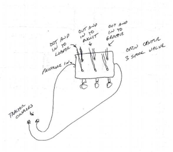
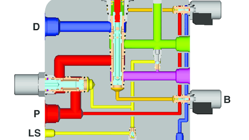
Open center hydraulic valve diagram. The Hydraulic Institute offers a framework for this, and a quality pump vendor should also be able to support system assessments. IMAGE 2: Example of a pump station with integrated VFDs and multiple jockey pumps to provide constant discharge pressure and automatic staging to meet demands of 15 to 600 gallons per minute. This should all look the same for (870/970/1070, and possibly 990 as well) This pic of the U-shape hardline, is the outlet (upper left banjo/bolt) from the pump, to the inlet (upper right banjo/bolt) of the loader SCV valve . The lower left banjo/bolt is from the Power Beyond port of the loader SCV valve, feeding the 3pt hitch. Open-center control block MO-16, 22, 32 64354 ... Contains the outer dimensions, all connections and the hydraulic circuit diagram of the control block. Offer drawing ... Directional valve A control block segment with 1 spool axis; also referred to below as a "valve section". Electric tipping valve operated by switch to suit light duty tipper trucks. Open center hydraulic scheme according to CE standards. - Built-in check and adjustable relief valves. - Either Chassis or tank (DSE kit) mounting options. - Mechanical End-of-stroke integrated into the relief valve. - Ready for pressure signal switch mounting.
4.6. #6 Pressure Compensated Flow Valve. 4.7. #7 Pinch Valve. 4.8. #8 Globe Valve. 4.9. #9 Diaphragm Valve. 4.10. #10 Ball Valve. 5. Conclusion. The valves which are mainly used to regulate the flow of fluid in hydraulic circuits are known as "flow control valves". The flow control valves are widely available in many different types ... Created by experienced hydraulic engineers.Learn the basic principles that drive every machine. Understand hydraulic circuits and learn how to solve breakdowns.. Specialist courses for all levels. Try a sample course module. Proportional pneumatic tipping valve to suit medium-heavy duty tipper trucks. Operated by N-FORCE. Open center hydraulic scheme accordino to CE standards. - Built-in check and adjustable relief valves (pilot type). - Nodular cast-iron body for pressare up to 400 bar - Either Chassis or tank (DSP kit) mounting options. Using particle swarm optimization (PSO) to optimize the installation position of the hydraulic cylinder at hip joint and knee joint. • Due to the dynamic characteristics of hydraulic actuators affect the stability of hydraulic system in a great extent, established the mathematical model of non-symmetric hydraulic cylinder system of zero- opening four-way slide valve, through Bode diagram and ...
Kubota l3400. The main concern with open vs closed system is that the open center requires a continuously-flowing "loop" of fluid through the system, dumping back into the tractor's tank at low pressure, if that makes sense. If interrupted, will dead-head the hydraulic pump and cause damage. A valve lifter (sometimes referred to as a tappet or cam follower); follows the contour of the camshaft lobe and transfers that motion, to open and close the valves. Valve lash adjustment is a necessary maintenance requirement, for engines without hydraulic valve lifters. [Ford Focus Rear Brake Diagram] - 9 images - fuses and relays box diagram ford taurus 2000 2007, ford fiesta 1995 1999 fuse box diagram auto genius, In strip rolling, hydraulic automatic gauge control (HAGC) system is the key element to guarantee the precision of strip gauge. The stability of the kernel pressure closed loop (PCL) in the HAGC system plays an essential role in guaranteeing the rolling process with high performance. Nevertheless, there is some difficulty in exploring the instability mechanism of the HAGC system due to the ...
Your dreams are next door
A diagram of the designed electronic circuit is presented in Figure 4. The DCCDuino Nano Nano connects to the measurement unit, the STP16NF06 N MOSFET, 60 V, 16 A, GDS, and an electronic solenoid valve. The wire leads, used to count the number of drops passing through the system, were housed just downstream of the narrow orifice . Water drops ...

Hydraulic Four-Way Valves | Hydraulic Valve
P&ID Valves Symbols and Their Usage. Provide various lifelike valves symbols, including ball valve, check valve, control valve, motor valve, hand valve, and 3D valve. Vector valves symbols help you create high clarity P&IDs. A wide range of pre-drawn P&ID valve symbols are included in Edraw.

Directional Control Valve Basics - Part 2 - YouTube
Process Valves for Air, Water, Liquids, and Steam. STC's high performance line of solenoid process valves offer a wide range of capabilities to suit your unique operating conditions. Several materials are available, including brass, 304 Stainless Steel, 316 Stainless Steel, PTFE (Teflon), and aluminum. ATEX and Explosion-Proof coil options, as ...

FluidSim hydraulic open circuit system | Download ...
In stock - Check Store Inventories. # 17708. Product Overview. Specifications. 3/4 inch ports and 1/2 inch outlets. 2 way power for use with log splitters. Detent for auto return. Open center. Adjustable pressure relief valve.
Hydrauoic System Troubleshooting and Maintenance
Hydraulic servo shaking table is an essential testing facility to simulate the actual vibration situation in real time. As a parallel mechanism, multiaxis hydraulic servo shaking table shows strong coupling characteristic among different degrees of freedom. When the multiaxis hydraulic shaking table moves to one direction, some unnecessary related motions will appear in other directions, which ...

Image from page 279 of "Railway and locomotive engineering : a practical journal of railway motive power and rolling stock" (1901)
Here are a number of highest rated Understanding Hydraulic Symbols pictures on internet. We identified it from obedient source. Its submitted by handing out in the best field. We resign yourself to this nice of Understanding Hydraulic Symbols graphic could possibly be the most trending topic following we share it in google lead or facebook.
Figure 11.71 ISO Valve Symbols
It consists of a worm-and-ball bearing nut steering gear with a hydraulic rack piston centered along the worm shaft, which can assist in moving the nut in any direction through hydraulic pressure.A reaction contact valve is linked to the worm shaft thrust bearing through a link and actuator lever. Any moment of the thrust bearing causes the control valve to move which opens and closes the oil ...

MTDC Pubs, Maintaining Constant Pressure on a Compaction ...
Diaphragm valves are characterized by a flexible disc that contacts a seat at the top of the valve body and forms a seal. The diaphragm is flexible and pressure-responsive; it transmits force to open, close, or control a valve. While diaphragm valves are related to pinch valves, they use an elastomeric diaphragm rather than an elastomeric liner in the valve body.
Open Center Hydraulic question - Yesterday's Tractors
2010 hydraulic backpressure. My early model 2010 Wheel (industrial backhoe) has had a variety of over-pressure problems ever since i ended up with it: leaks, blown seals, banging in the lines, etc. It's an H-L-R transmission with power steering. I teed in a pressure gauge at the output of the cooler, and found that once you raise the RPMs, the ...
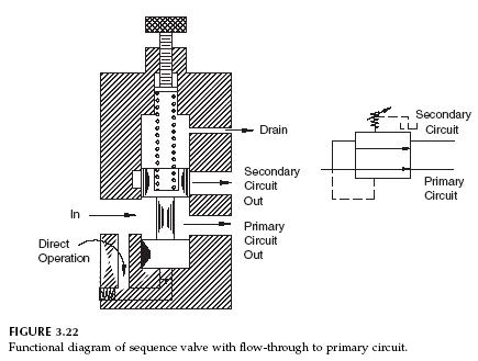
Hydraulic Sequence Valve Operation | Hydraulic Valve
In case of doubt, only metric values are valid. Subject to change, status 2021-01-12 16:52:39. Products. Product Groups. Mobile Hydraulics. Mobile controls. Power brake valves. LT 05.

A look up shot of the world trade centre on a dreary rainy day in NYC.
Muncie Power Products is a leading manufacturer of power take-offs (PTO), hydraulic components such as pumps, motors, cylinders, valves and reservoirs, and snow & ice removal products. 1-800-367-7867 CONTACT
27 Cross Hydraulic Valve Diagram - Wiring Database 2020
The hydraulic diagram of the hoist gear is perfect for selling spare parts. But not for the image of the manufacturer to whom we will blame a very low lifespan. You must absolutely add a normally closed 2/2 directional valve plus ø7mm nozzle between the B of the A6VM motors and the A7 filter.
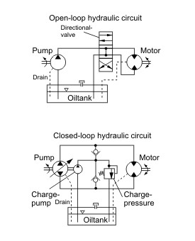
Hydraulic Circuits, Open vs. Closed - Hydra-Tech
The info: Monoblock Hydraulic Directional Control Valve, 2 Spool, 11 GPM. SKU: P402-2A1. This manual monoblock valve is a hydraulic directional control valve. These valves are used to start and stop fluid flow into hydraulic cylinders or hydraulic motors.

Prince RD513AA5A4B1 Directional Control Valve, Monoblock ...
Find many great new & used options and get the best deals for Nimco hydraulics, control valve , joystick block, loader cables at the best online prices at eBay! Free shipping for many products!

Directional control valve 1-spool hydraulic solenoid 80 l ...
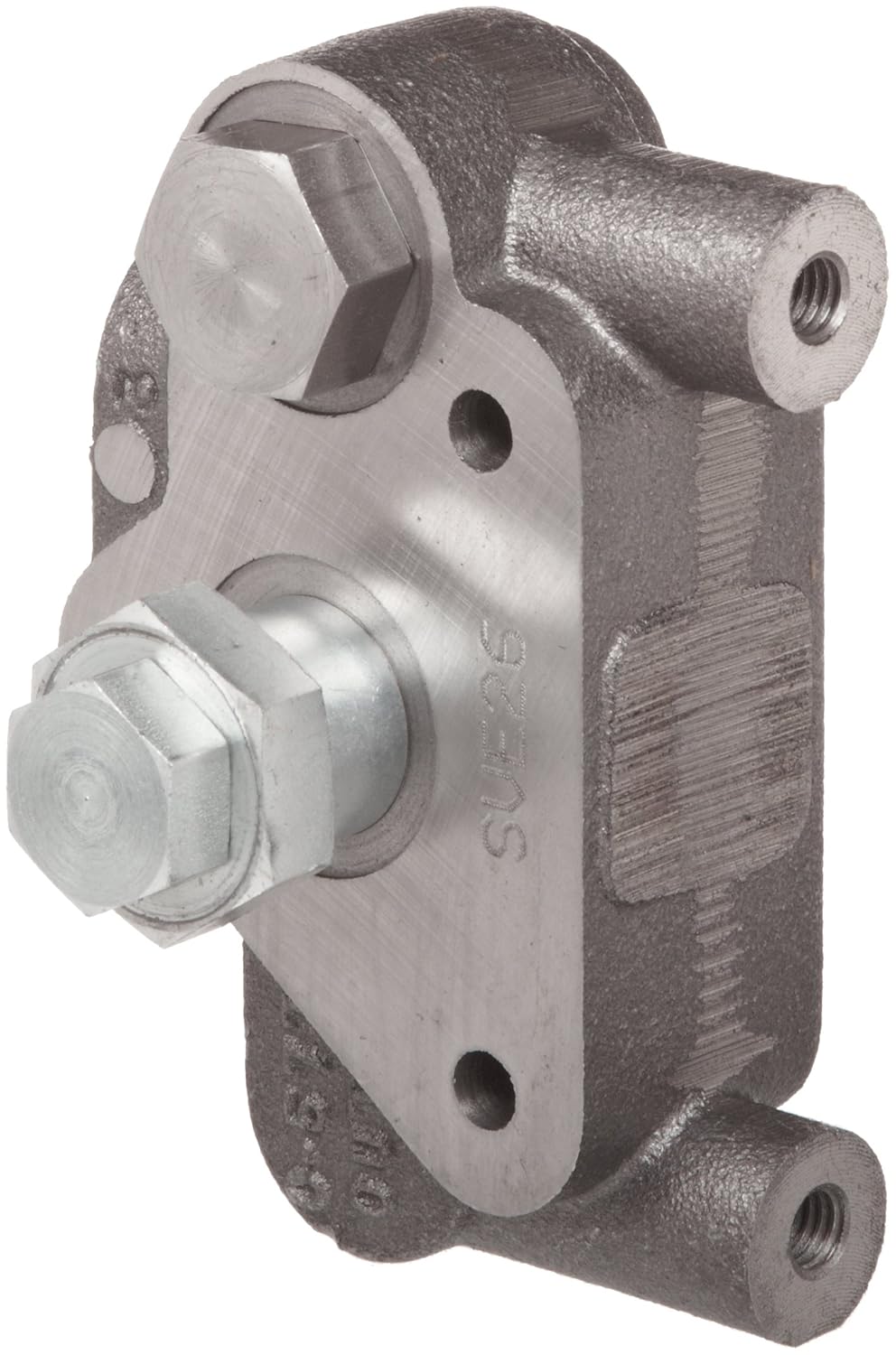
Prince SVE26 Directional Control Valve Open Center Outlet ...
Hydraulic systems | diagrams circuit

Schematic diagram a) components of hydraulic steering ...

BLM | George Floyd Memorial | June 9, 2020

Figure 2-6. Typical Open-Center Spool Selector Valve.

Aircraft systems: Basic Hydraulic Systems

Disposition

DIFFERENCE BETWEEN CLOSED LOOP AND OPEN LOOP HYDRAULIC ...

Brand Hydraulics Log Splitter Valve, Model# PLS755T4JRSH ...

Directional valve Manually operated - miniBOOSTER ...

Cross Hydraulic Valve Diagram - General Wiring Diagram
Hydraulics, open-center, pressure compensated (PC) - 21.1 gpm

Closed Center Conversion | Cross Mfg.

Molino Argentino, Oprn Door, Argentina

Hydraulic Circuits: Hydraulic Closed-Center System Using ...

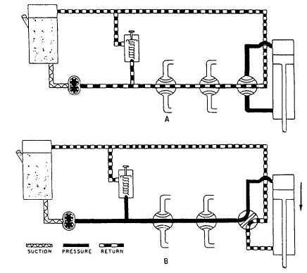
Hydraulic Circuits: Open Center Circuit | Hydraulic ...

3 Spool 20 Series Prince Stack Valve Closed Center | Stack ...
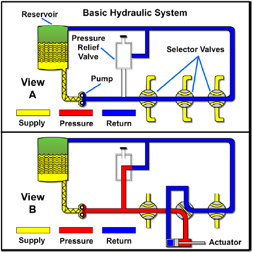
Basic Diagrams and Systems | Engineering Library

Prince RD515EC5A4B1 Directional Control Valve, Monoblock ...

Yuken Directional Valve Wiring Diagram - Hanenhuusholli

HYDRAULIC 4 WAY flow diverter valve 3/4" BSPP 24gpm open ...

455 - DRILL, GRAIN Open/Closed Center Hydraulic Kit ...

Understanding hydraulic systems - Grainews
0 Response to "38 open center hydraulic valve diagram"
Post a Comment