39 crystal radio circuit diagram
A crystal radio, or crystal set as it is sometimes called, is a radio that only uses the power of the radio waves picked up by the antenna to generate the sound heard in the head phones. The reason it is called a crystal set is because they use a mineral crystal as a diode for the detector in the circuit. Crystal Radio web site. Crystal radio plans, crystal radio circuits, crystal radio schematics are all right here. Sound powered headphones and how to use them on crystal radios. Crystal Radios, Crystal Set, Crystal Sets, Catswiskers, Science Fair Crystal Radio, and much more!
This crystal radio is a homemade copy of the Heathkit CR-1 Crystal Radio from the 1950's. It is built in a 6 x 3 x 2 inch deep plastic box, the same size as the original. It uses a double tuned circuit with two ferrite core coils and 100 strand Litz wire.

Crystal radio circuit diagram
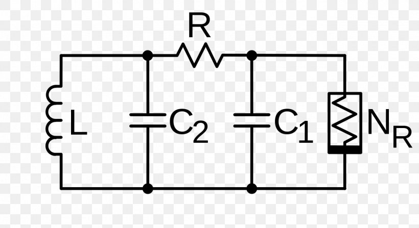
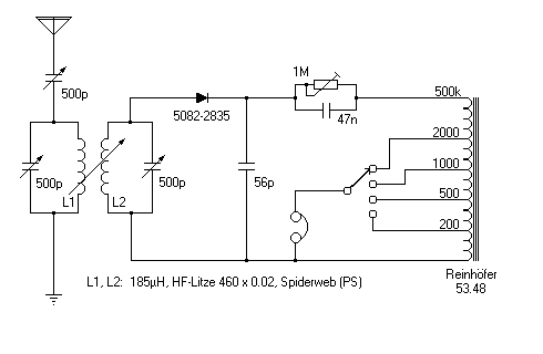
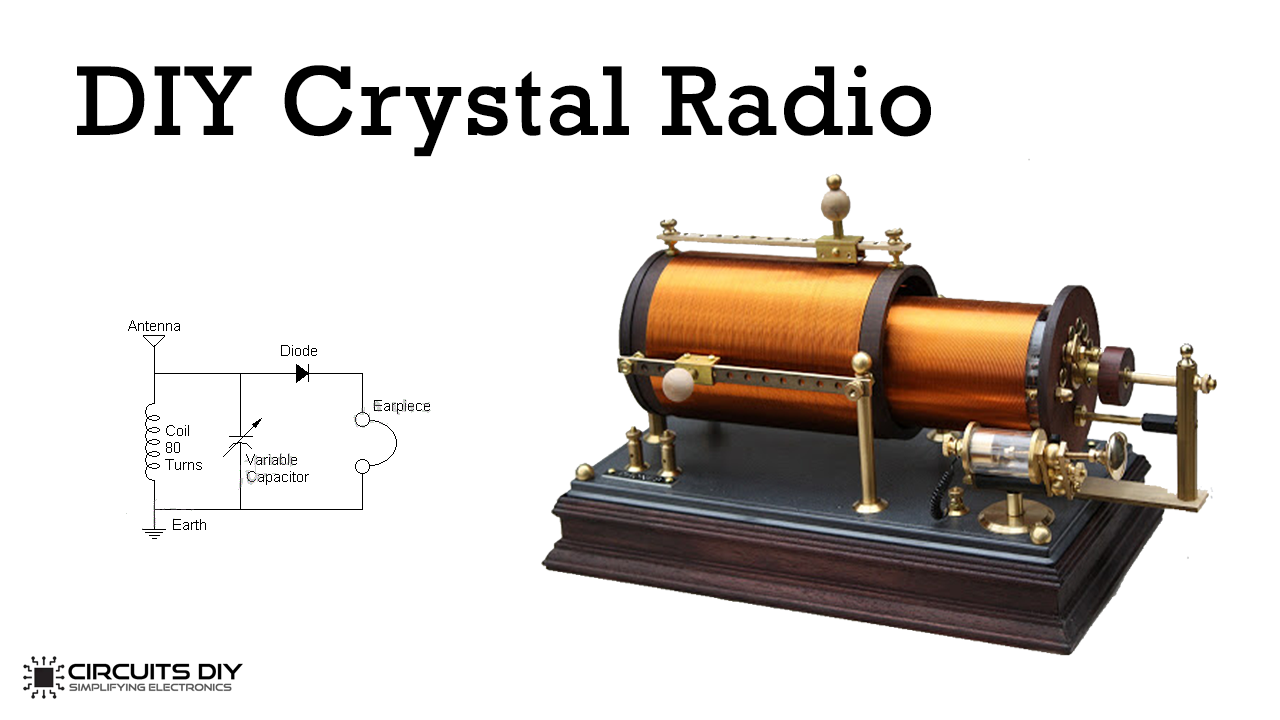
After finishing the loop associate all parts like germanium diode, variable capacitor, coil and earpiece to make a crystal radio as appeared in the circuit diagram. After building the radio associate the longest receiving wire to the radio circuit and go outdoors to the window and attach it to any tree or simply put it out from the window. An earpiece needs much less power than a normal speaker and can make enough sound to be barely heard. Some circuits use a crystal radio circuit to detect and tune the signal. Then they add a small amplifier circuit to drive a normal speaker. Circuit diagram 1 Circuit diagram of the crystal receiver, which we are going to design for maximum sensitivity at weak signals. This can be a detector circuit of a 2 circuit receiver. But also a receiver with loop antenna. RP represents the losses in coil L and tuner capacitor C1
Crystal radio circuit diagram. 17-11-2018 · 1# Crystal Oscillator circuit using 74LS04. The oscillators or frequency generators provide a waveform out in various forms. For example, sine wave, Triangular waveform, and square wave. They generate the frequencies to be a base time. To control an electronic circuit. The crystal oscillator circuit like this get popular uses in digitals. Piezoelectric Transducer Circuit. The working of a basic piezoelectric transducer can be explained by the below figure. Piezoelectric Transducer Circuit. Here quartz crystal coated with silver is used as a sensor to generate a voltage when stress is applied on it. A charge amplifier is used to measure the produced charge without dissipation. 06-09-2020 · When we say to an astable multivibrator circuit. Most people think of IC-555. It is famous for making pulse generator and timer. But this time, I recommended, CD4047. It is also an Astable multivibrator circuit on CMOS chip. We can use it in many circuits. Most used in an AC inverter, Square wave generator, LED flasher, and more. 05-09-2021 · Radio stations broadcast on medium-wave bands and send signals into the air all around us. Only a few simple parts are needed to pick up AM radio waves: some electronic components, wire, a paper tube, and a speaker. Assembly is simple, and...
pear in the several crystal booklets published pre- viously by our Company. We believe the engineer, service technician, transmitting radio amateur, and hobbyist all will find items of interest in this new collection of circuits and data. It is believed further that the items contained in this booklet will What I was searching for is a small AM radio that I got in a box of cereal in the 50's. It had a button type earphone. Very small. All I had to do was to hook up 1 alligator clip to a ground, like a water pipe. Tuning was made with a small rod inside a tube. All you had to do was move the rod in or out till you got a station. Anybody remember ... For more crystal radio circuits, simple one-transistor radios, and more advanced low transistor count radios. Regency TR1: First mass produced transistor radio, 1954 . The circuit in the figure below is an integrated circuit AM radio containing all the active radio frequency circuitry within a single IC. Capacitive Load on Crystal 80 7.3. Pierce Circuit 83 7.4. Colpitts Circuit 84 7.5. Modified Meacham Circuit 85 7.6. Butler Harmonic Circuits, C-tap89 7.7. Butler Harmonic Circuits, L-tap93 6. TRIMMING THE CRYSTAL FREQUENCY101 9. THE START-UP PROBLEM 103 9.1. Biasing ICs 103 9.2. Biasing Discrete Transistors 105
Radio receiver design includes the electronic design of different components of a radio receiver which processes the radio frequency signal from an antenna in order to produce usable information such as audio. The complexity of a modern receiver and the possible range of circuitry and methods employed are more generally covered in electronics and communications … Crystal Radio Circuits. You'll find these useful after an em-pulse : 40 PDFs of old radio magazine articles ( most unidentifiable ) about crystal radio receivers--"101 Receiving Circuits" "Construction of Radio Receiving Apparatus" ( Everyday Mechanics) "A Crystal Set ... Crystal Radio Schematic Selector Page. Hi friends. I suppose that some of you have noticed that I built a lot of crystal radios. Some might say that is an understatement. The selecting of a radio that you might want to make for yourself sometimes starts with looking at the schematic diagram. This is understandable as you can quickly gauge the ... schematic diagram of a basic crystal set. The tuned circuits in a crystal radio are composed of a coil (inductor) and a capacitor, usually variable, to allow tuning the circuit to the desired frequency. A crystal set can be made with a single tuned circuit (the detector coil), or with an added
File:Two slider crystal radio circuit.svg - Wikimedia Commons
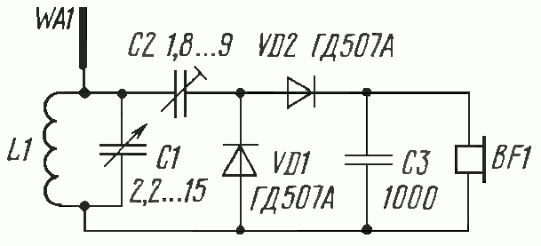
How It Works. The receiver employs a double-tuned circuit feeding a crystal-diode voltage-doubler/detector which drives a small speaker. In operation, r.f. signals picked up by the antenna system are induced into coil L2 from the coil L1.The desired signsl is selected by tuned circuit C1a-L2 and coupled through capacitor C2 to a second tuned circuit C1b-L3, which improves the selectivity by ...

Dave's #6 Crystal Radio Schematic | Radio, Crystals, Antique ...
Crystal Radio Plans and Circuits and parts of books This section contains 174 articles at the present time (articles are numbered) Many articles have multiple plans! Information Donated In Part By The Following Persons Mike Tuggle (Hawaii), Richard O'Neill, Lou Blasco, Mike Peebles, Andy Klute, Evan Haydon,
FM Crystal Radio Receivers
Transmitter Circuit Diagram. Transmitter Circuit Explanation. Different voice modes. The Receiver. How to use this Walkie talkie. The Idea: This project utilizes FM radio as receiver and FM transmitter to send voice. A person who wants to communicate with the other will have a set of FM radio and FM transmitter and same with the other person.
The "UnFETtered Crystal Radio! - circuit diagrams, schematics ...
Build a Crystal Shortwave Radio. This project combines two popular themes from radio history—crystal radios and shortwave (SW) listening. It's designed from scratch by our non-resident engineer Walter Heskes.. Despite all of the advances in modern electronics, there are thousands of crystal sets in daily use throughout the world.

Nostalgic Crystal Radio :: circuit diagrams
This is what it looks like: It comes with a normal 3.5 mm jack at the end of it, but for a crystal radio, you'll want to cut that off and expose the two wires at the end. It's only one earpiece, but you need two wires in order to complete the circuit properly. We'll get into that a little more specifically below.
Amplifier for crystal radio earphone
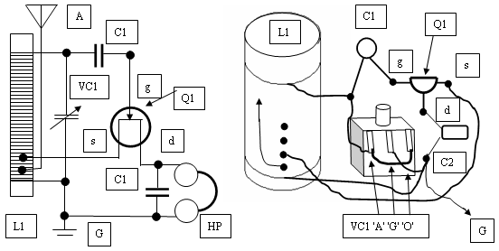
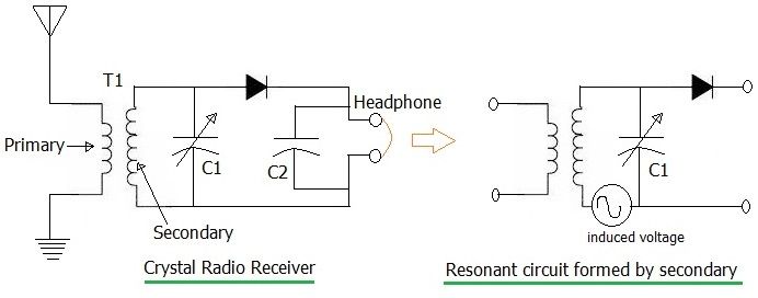
Imagine that we have a crystal radio like the one above connected to a long wire antenna. The passing radio wave from our station induces a tiny high frequency voltage on our antenna wire. The antenna is connected to the antenna coil (coil on the top of the diagram) with its antenna tuning capacitor to the left and below it.

kjs crystal radio, big litz
Surf Simulator Circuit Diagram When The Siren Sounds - A Useful Circuit ... CMOS Crystal Frequency Multiplier ... (Radio) Wire Tracer (Transmitter) Wire Tracer (Receiver) Low Power FM Transmitter Simple RF Detector For 2M One Transistor …

kjs crystal radio, fleming
Crystal Oscillator Diagram. Source: Wikimedia Commons. In simpler terms, a crystal oscillator circuit is the electronic circuit board that houses the device that produces a specific frequency. It's also an electronic oscillator circuit that works with a vibrating crystal's mechanical resonance—to generate a consistent frequency.

Antique Radio Forums • View topic - Crystal set construction ...
Circuit Operation. The circuit appeared above is utilizing a transistor 2N3904 as a preamplifier and an IC LM386 which is amplifying the sound signals originating from transistor to drive a smaller than normal 8 ohms loudspeaker or earphones. Furthermore, this is a crystal radio speaker for enhancing the output sound to a crystal earphone or phone receiving earphones.

File:Crystal radio receiver block diagram.svg - Wikipedia
The circuit also helps to prevent any incidents of the short course. Some circuit boards also have USB charging options for convenience. You will have to use a USB cable for this purpose. The Bluetooth receiver circuit board will have an antenna used to receive the signal from your smartphone or Bluetooth device.

How to make a radio receiver circuit - Quora
Crystal radio circuits & functions. There are very many different circuits that can be used for a crystal radio. Although there are differences in these circuits, the operation is basically the same. A typical crystal radio circuit is shown below and from this it can be seen how a crystal radio works. Basic crystal radio circuit

File:Common crystal radio circuit.svg - Wikimedia Commons
Bluetooth Circuits A Bluetooth circuit is the central part of a Bluetooth and contains components such as the integrated circuit, capacitors, and power source. The course supports wired-in audio, wireless stereo, Bluetooth module, and many more. We have professional standard reviewers that ensure strict quality control measures in every production process. We leverage advanced …
Remembering the Crystal Radio | Nuts & Volts Magazine
Crystal radio. Build this Crystal Radio A crystal radio is a radio that does not require a power source other than the energy contained in the signal being received. With a good antenna, like the random wire you can build by following the instructions on this web site, strong local stations will be very discernable during the day and at night even a few distant "skip" stations may be picked up.
Learning Electronics — 2. Fun with Crystal Radio and ...
Crystal Radio Concept. The only downside of this radio concept is the requirement of a very long antenna and a deep earthing, therefore this unit is not something which you can carry in your pocket, nevertheless the extreme simplicity and the no power operation feature make this circuit an amazing device.
Build a High End Multiband Crystal Radio - Alvenh Channe
Crystal radio circuit with variable coupling and tapped coil. This is a very elegant method for adjusting the sensitivity and selectivity to obtain the required performance. During the days when crystal radios or crystal sets were the radio of choice for cost reasons as well as the availability of components, etc, a vast number of circuits came ...

Free-Power AM Radio
A crystal radio was the very first circuit I built. I was 9 at the time, which makes it, what, 49 years ago. Still remember the first time I actually heard a station come in.
Electronic Circuit Chua's Circuit Circuit Diagram Crystal ...
SIMPLE SCHEMATIC, LONG ANTENNA. Crystal sets receive AM (Amplitude Modulated) radio stations by using a simple demodulation scheme. The schematic is shown in Figure 3. FIGURE 3. Early crystal radios used a natural galena crystal instead of a germanium diode to detect the audio modulation.
crystal radio receiver basics | crystal radio circuit
The circuit is quite simple but many pitfalls await the novice. The first precaution is most important! The crystal radio works best with a long, high outdoor antenna but the beginner may not fully appreciate the danger of bringing such a wire into the house.

Crystal radio - Wikipedia
A typical circuit diagram for a Crystal Set Radio is given below where inductor or coil L1 is tuned by variable capacitor VC1 to the transmitter frequency. Want to make a radio. A crystal radio receiver also called a crystal set or cats whisker receiver is a very simple radio receiver popular.

How a Crystal Radio Works
from Berlin. Here is the diagram: In the "Strays" section of QST for July, 1944, another mention is made of the razor blade foxhole radio: According to Toivo Kujanpaa, a licensed ham op stationed on the Anzio Beachhead, several of the radio men there rigged up a field version of a "crystal" set using a razor blade for a detector. Their

Simplest DIY FM crystal receiver in Germany. Is so good that ...
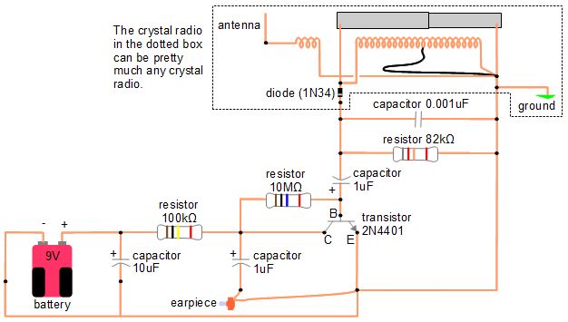
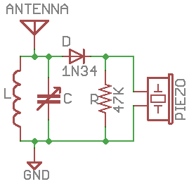
The 1N34A germanium diode in this crystal radio circuit is sensitive to light of all kinds. It responds to sunlight, light-bulbs, laser, flashlights, and even candlelight! The laser will work to activate sound from the radio from many feet away, but only when the laser light is actually moving across the light-sensitive diode.
Having a series instead of parallel LC circuit in a crystal ...
Circuit diagram 1 Circuit diagram of the crystal receiver, which we are going to design for maximum sensitivity at weak signals. This can be a detector circuit of a 2 circuit receiver. But also a receiver with loop antenna. RP represents the losses in coil L and tuner capacitor C1

How to build a sensitive crystal receiver
An earpiece needs much less power than a normal speaker and can make enough sound to be barely heard. Some circuits use a crystal radio circuit to detect and tune the signal. Then they add a small amplifier circuit to drive a normal speaker.

Portable crystal radio using a loop antenna
After finishing the loop associate all parts like germanium diode, variable capacitor, coil and earpiece to make a crystal radio as appeared in the circuit diagram. After building the radio associate the longest receiving wire to the radio circuit and go outdoors to the window and attach it to any tree or simply put it out from the window.

Useful Components Choccy Block Crystal Radio
FM Crystal Radio Circuit

3D Printed FM Crystal Radio

A Simple Radio Receiver
Spy Crystal Radio
Crystal Radio Circuit

Crystal radio Facts for Kids
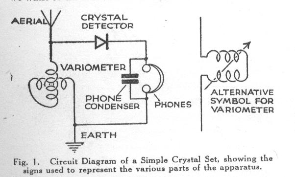
variometer crystal set spiderweb coil

Dave's Homemade Radios - Circuits Page
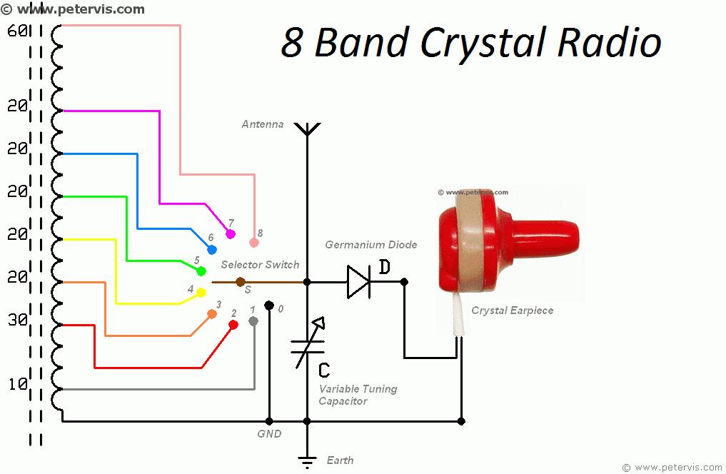
8 Band Crystal Radio Circuit Diagram
New double-tuned crystal set - The RadioBoard Forums

Crystal Radio Circuits: Crystal Set Circuits » Electronics Notes

Crystal Radio Schematic | Radio, Crystals, Shortwave radio

Crystal Radio with Amplifier | Circuit Diagram
How to Make / Build a Crystal Radio
0 Response to "39 crystal radio circuit diagram"
Post a Comment