37 In A State Machine Diagram, A State Is Represented By A(n) _______.
ch 5 Flashcards - Quizlet In a state machine diagram, a state is represented by a(n) ____. oval True or False: In an activity diagram, a separate use case may used as part of the workflow. PDF Sequential Circuit and State Machine State Transition ... - The state machine is represented as a state transition diagram (or called state diagram) below - One step (i.e., transition) can be taken whenever there is a clock signal State Transition Diagram (or State Diagram) S0 S3 S1 S2 Coover Hall Sweeney Hall Durham Center Parks Library Start 3 • States can be coded as binary combinations of ...
PDF Finite State Machines - University of Washington Spring 2010 CSE370 - XIV - Finite State Machines I 3 Example finite state machine diagram 5 states 8 other transitions between states 6 conditioned by input 1 self-transition (on 0 from 001 to 001) 2 independent of input (to/from 111) 1 reset transition (from all states) to state 100 represents 5 transitions (from each state to 100), one a self-arc

In a state machine diagram, a state is represented by a(n) _______.
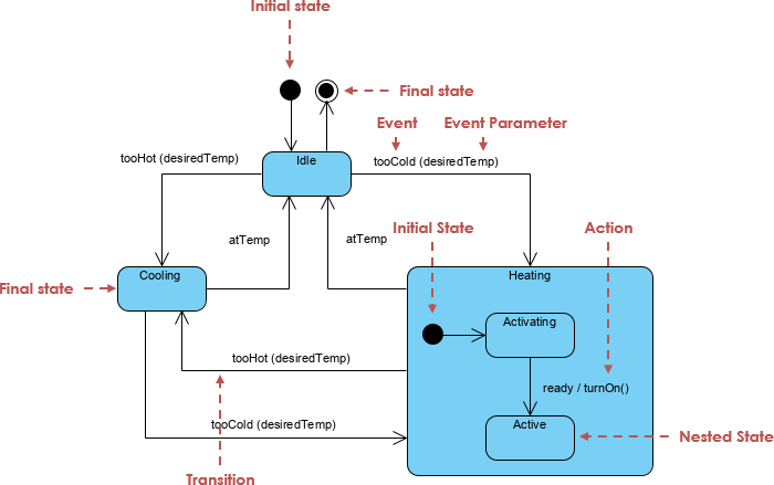
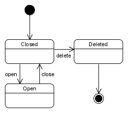
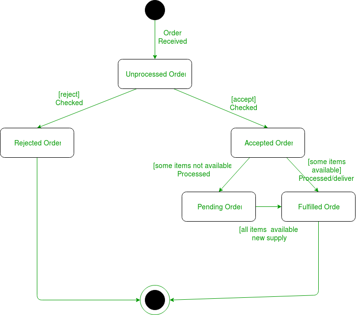
What is State Machine Diagram? UML State Machine Diagrams (or sometimes referred to as state diagram, state machine or state chart) show the different states of an entity. State machine diagrams can also show how an entity responds to various events by changing from one state to another. State machine diagram is a UML diagram used to model the dynamic nature of a system. MGS2PM Flashcards - Quizlet In a state machine diagram, a state is represented by a(n) ____. oval. Which of the following is NOT a step in the development of a state machine diagram? a. List all the status conditions for an object. b. Identify state exiting transitions. ... A state machine diagram is used to document the states and transitions of a(n) _____. PDF LECTURE #16: Moore & Mealy Machines - University of Florida - A binary number can represent 2n states, where n is the number of bits. - The number of bits required is determined by the number of states. Ex. 4 states requires 2 bits (22 = 4 possible states) Ex. 19 states requires 5 bits (25 = 32 possible states) - One flip-flop is required per state bit. Steps to Design Sequential Circuits: 1) Draw a ...
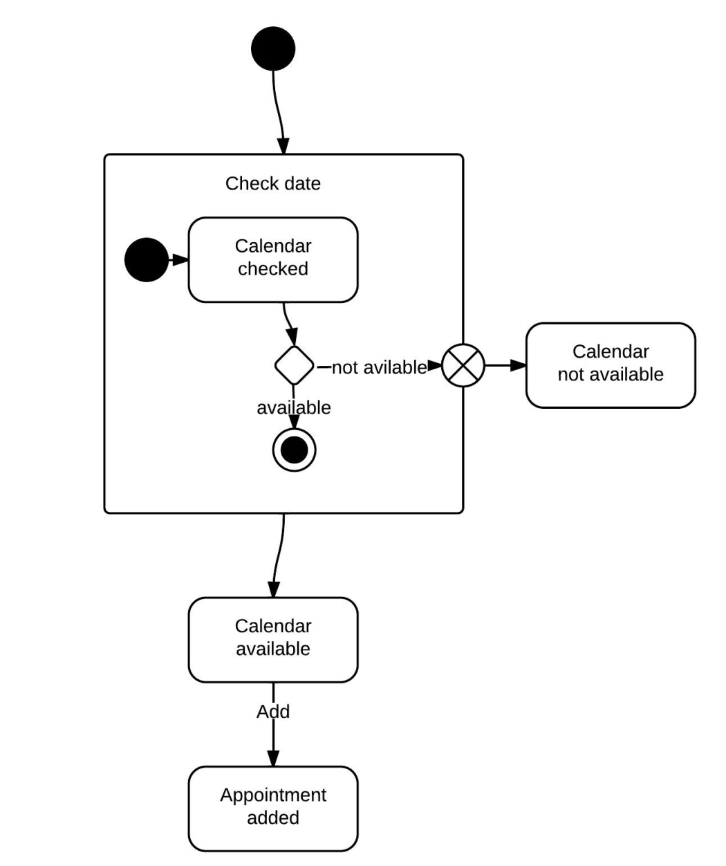
In a state machine diagram, a state is represented by a(n) _______.. Free Body Diagram Questions and Answers - Study.com Free Body Diagram Questions and Answers. Get help with your Free body diagram homework. Access the answers to hundreds of Free body diagram questions that are explained in a way that's easy for ... IEC 61131-3: The State Pattern - Stefan Henneken State machines can be very well represented as a UML state diagram. A UML state diagram describes an automaton that is in exactly one state of a finite set of states at any given time. The states in a UML state diagram are represented by rectangles with rounded corners (vertices) (in other diagram forms also often as a circle). Finite State Machine | Our Pattern Language FSM can be described as a state transition diagram. For example, figure 1 depicts state transition diagram where Q = {s 0, s 1} and Σ = {0, 1}. For complex problems, the difficulty in representing the system as FSM is how to deal with the state explosion problem. A system with n variables that can have Z values can have Z n possible states. PDF CHAPTER VIII FINITE STATE MACHINES (FSM) - gatech.edu STATE DIAGRAMS ELEMENTS OF DIAGRAMS FINITE STATE MACHINES •STATE MACHINES-INTRODUCTION-MEALY & MOORE MACH.-SYNC. & ASYNC SYSTEMS • A state diagram represents a finite state machine (FSM) and contains • Circles: represent the machine states • Labelled with a binary encoded number or reflecting state.
PDF IV. State and Activity Diagrams States are supposed to represent longer-running activities (or ... For UML state diagrams, states can be composed into nested states, or superstates. Such compositions make it possible to view a state diagram at different levels of abstraction. A superstate c onsists of one or more states. State Machines - Documentation A State Machine diagram falls under the behavioral diagramming family. The behavior of objects of a Class is defined in terms of States and Events, using a State Machine connected to the Class under a construction.. The State Machine is a specification of the sequence of states an object or an interaction undergoes in response to events during its life, combined with its responsive actions. All You Need to Know about State Diagrams A State Machine Diagrams shows the possible states of the object and the transitions that cause a change in state. Take a look at the State Machine Diagram below. It models the transitioning of states for an incident. Such a state diagram focuses on a set of attributes of a single abstraction (object, system). State Machine Diagram Example: A ... PDF Finite State Machines - Massachusetts Institute of Technology For N states, use ceil(log 2N) bits to encode the state with each state represented by a unique combination of the bits. Tradeoffs: most efficient use of state registers, but requires more complicated combinational logic to detect when in a particular state. Choice #2: "one-hot" encoding For N states, use N bits to encode the state where ...
Conversion from Moore machine to Mealy machine - Javatpoint To convert Moore machine to Mealy machine, state output symbols are distributed into input symbol paths. We are going to use the following method to convert the Moore machine to Mealy machine. Method for conversion of Moore machine to Mealy machine. Let M = (Q, ∑, δ, λ, q0) be a Moore machine. The equivalent Mealy machine can be represented by M' = (Q, ∑, δ, λ', … Finite-state machine - Wikipedia The turnstile state machine can also be represented by a directed graph called a state diagram (above). Each state is represented by a node (circle). Edges (arrows) show the transitions from one state to another. Each arrow is labeled with the input that triggers that transition. An input that doesn't cause a change of state (such as a coin input in the Unlocked state) is represented … PDF Example finite state machine In this diagram, the bubbles represent the states, and the arrows represent state transitions. The arrow labels indicate the input value corresponding to the transition. For instance, when the elevator is in the Ground state, and the input is Up, the next state is First. Machine learning for alloys | Nature Reviews Materials 20.07.2021 · Machine learning (ML) has been transforming materials science. The past two decades have been marked by a dramatic increase in the amount of generated data, and ML provides the essential tools to ...
State Machine Diagram - UML 2 Tutorial | Sparx Systems
State Diagram and state table with solved problem on state ... In this diagram, each present state is represented inside a circle. The transition from the present state to the next state is represented by a directed line connecting the circles. If the directed line connects the circle itself, which indicates that there is no change in the state (the next state is the same as the present state).
State Machine Diagram Tutorial | Lucidchart
UML State Machine Diagrams - Overview of Graphical Notation State machine diagram is a behavior diagram which shows discrete behavior of a part of designed system through finite state transitions. State machine diagrams can also be used to express the usage protocol of part of a system. Two kinds of state machines defined in UML 2.4 are behavioral state machine, and protocol state machine.

Finite-State Machine - an overview | ScienceDirect Topics
State Machine Experiment - TESSAL Center This circuit is easily built using a decoder and OR gates. A Finite State Machine can be represented by a transition diagram that shows what states are available and what input values cause a transformation from one state to another. The following transition diagram shows the states named as A, B, and C.
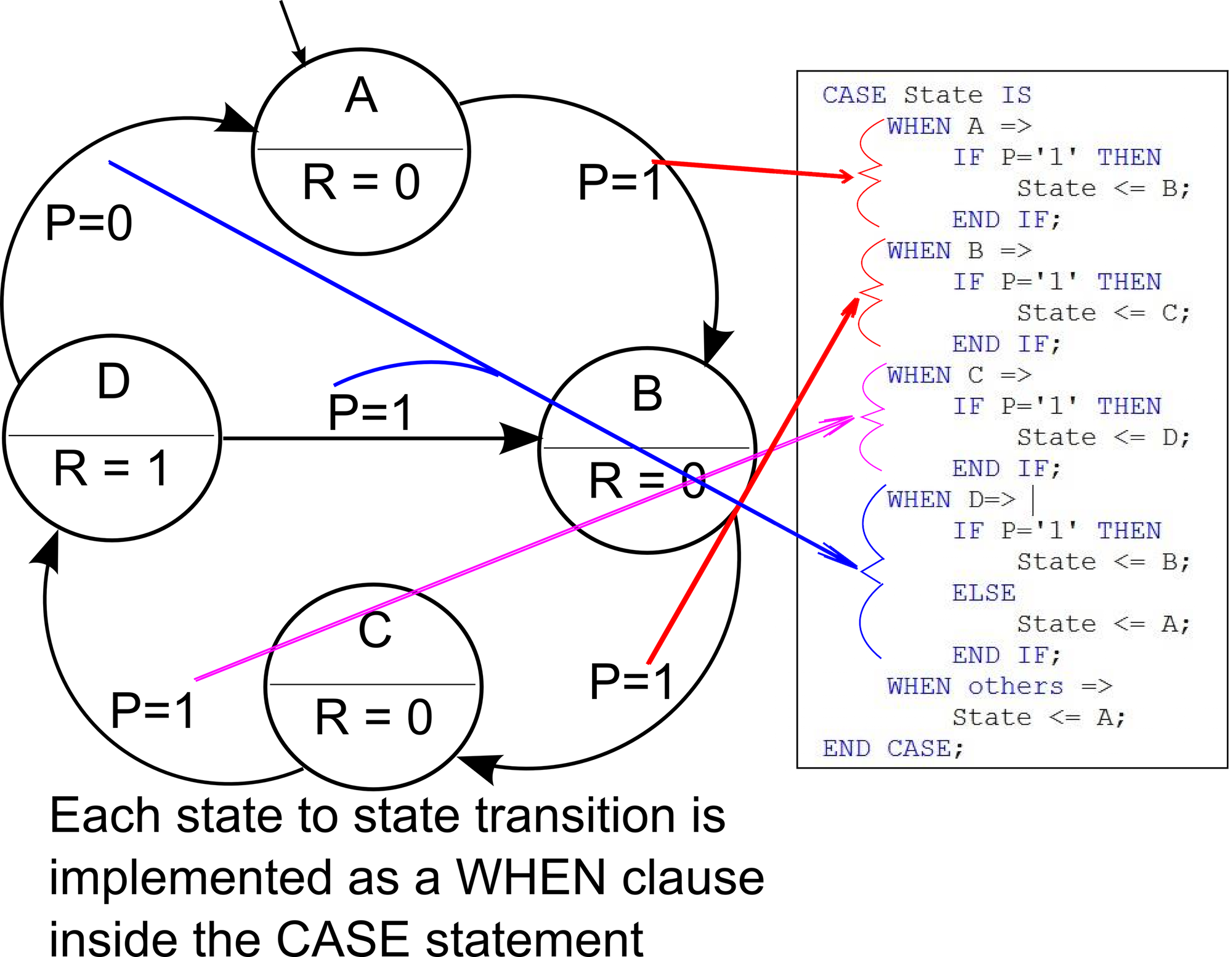
Implementing a Finite State Machine in VHDL - Technical Articles
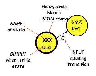
PDF Finite State Machines - University of Washington States represented by circles Transitions (actions) represented by arrows connecting states Lables on Transitions give / Note: We cover Mealy machines here; Moore machines put outputs on states, not transitions Finite State Machine: State Diagram with finite number of states

State Machine Diagram Chapter 5 Introduction Pages ppt download
Unified Modeling Language (UML) | State Diagrams ... A state diagram is used to represent the condition of the system or part of the system at finite instances of time. It's a behavioral diagram and it represents the behavior using finite state transitions. State diagrams are also referred to as State machines and State-chart Diagrams. These terms are often used interchangeably.

What is State Machine Diagram?
PDF Sequential Circuit and State Machine State Transition ... - The state machine is represented as a state transition diagram (or called state diagram) below - One step (i.e., transition) can be taken whenever there is a clock signal State Transition Diagram (or State Diagram) 2 S0 S3 S1 S2 Coover Hall Sweeney Hall Durham Center Parks Library Start • States can be coded as binary combinations of ...

State Machine Diagram vs Activity Diagram
PDF LabVIEW State Diagram Toolkit User Guide A state machine is a system with unique states and transitions that govern the execution flow of the system. In applications where distinguishable states exist, you create a state diagram to graphically represent a state machine. Within a state diagram, each state can lead to one or multiple states or can end the process flow.
ch 5 Flashcards | Quizlet
Week 3 Part 2 - Finite State Machine | 50.002 Output rules: \(f(S_i)\) for each of the \(k\) states. State Machine Diagram and the Truth Table. We can represent a state machine in two forms: state transition diagram or truth table. Suppose we have a simple digital lock machine, that will open only if we give the password: 0110. The following state diagram illustrates how that lock works:

UML 2 State Machine Diagrams: An Agile Introduction
PDF EE 109 State Machine Overview - University of Southern ... State Diagrams • Abstractly a state machine can be visualized and represented as a flow chart (or state diagram) - Circles or boxes represent state - Arrows show what input causes a transition - Outputs can be generated whenever you reach a particular state or based on the combination of state + input S0 Out=False S1 S2 out=True Input=1 ...
Unit 5 What is state? State Machine Block Diagram State Diagrams
PDF Finite State Machines - University of Washington States represented by circles Transitions (actions) represented by arrows connecting states Lables on Transitions give / Note: We cover Mealy machines here; Moore machines put outputs on states, not transitions Finite State Machine: State Diagram with finite number of states Even Odd Reset 0/0 0/1 1/1 1/0
All You Need to Know about State Diagrams
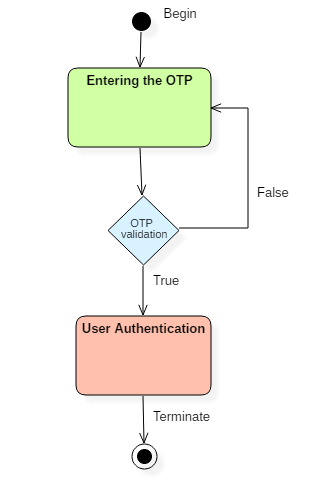
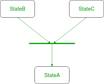
In a state machine diagram, a state is represented by a(n Refer to the diagram to the right. the firm represented in the diagram makes; The symbol that is used to initiate concurrent paths in a state machine diagram is what? Another name for a workflow diagram is a(n) _____ diagram. In a state transition diagram, the states appear as rounded rectangles with the state names inside.
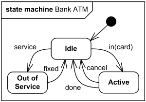
UML State Machine Diagrams - Overview of Graphical Notation
Finite-State Machine - an overview | ScienceDirect Topics An FSM can be represented using a state diagram (or state transition diagram) as an example in Fig. 5.28. Besides this, several state transition table types are used. A state transition table is a table describing the transition function of an FSM. This function governs what state (or states in the case of a nondeterministic FSM ) the FSM will move to, given an input to the machine. …

State Space Representations of Linear Physical Systems
PDF Finite State Machines Introduction We've looked at ... We now formally define such a finite state machine . We specify the variables . X. i - Represent system n inputs . Z. j - Represent system m outputs . Y. k - Represent internal p state variables . We define our finite state machine as a quintuple . M = { I, O, S, δ, λ} I - Finite nonempty set or vector of inputs . O - Finite nonempty set or ...
State Machine Diagram in UML | What is Statechart Diagram?
State Machine Diagram in UML | What is Statechart Diagram? Statechart diagrams provide us an efficient way to model the interactions or communication that occur within the external entities and a system. These diagrams are used to model the event-based system. A state of an object is controlled with the help of an event. Statechart diagrams are used to describe various states of an entity within the application system. There are a total of two types of state machine diagram in UML:
Finite State Machines
PDF Chapter 4 State Machines - MIT OpenCourseWare Here are a few state machines, to give you an idea of the kind of systems we are considering. • A tick-tock machine that generates the sequence 1,0,1,0, . . . is a finite-state machine that ig nores its input. • The controller for a digital watch is a more complicated finite-state machine: it transduces a
Unified Modeling Language (UML) | State Diagrams - GeeksforGeeks
PDF State Machines - ksuweb.kennesaw.edu state machine, but it is difficult to analyze if there are many states or inputs. Another, more visual way to represent the actions of a sequential circuit is with a state transition diagram .

State Machine Diagram Chapter 5 Introduction Pages ppt download
Class diagram - Wikipedia State diagram; Timing diagram; Use case diagram ; Hierarchy of UML 2.5 Diagrams, shown as a class diagram. The individual classes are represented just with one compartment, but they often contain up to three compartments. In software engineering, a class diagram in the Unified Modeling Language (UML) is a type of static structure diagram that describes the structure of …

What is State Machine Diagram?
Dynamic Model: Sequence and State Chart Diagrams Similar to a finite state machine diagram (computer theory) A state. is a condition satisfied by the attributes of the object (i.e. determined by the current values in the attributes) is represented by a rounded rectangle; A transition. is a change of state triggered by an external event, a condition, or perhaps time elapsed

State Machine Diagram - an overview | ScienceDirect Topics
PDF LECTURE #16: Moore & Mealy Machines - University of Florida - A binary number can represent 2n states, where n is the number of bits. - The number of bits required is determined by the number of states. Ex. 4 states requires 2 bits (22 = 4 possible states) Ex. 19 states requires 5 bits (25 = 32 possible states) - One flip-flop is required per state bit. Steps to Design Sequential Circuits: 1) Draw a ...
UML State Machine Diagrams - Graphical Notation Reference
MGS2PM Flashcards - Quizlet In a state machine diagram, a state is represented by a(n) ____. oval. Which of the following is NOT a step in the development of a state machine diagram? a. List all the status conditions for an object. b. Identify state exiting transitions. ... A state machine diagram is used to document the states and transitions of a(n) _____.
A simple guide to drawing your first state diagram — with ...
What is State Machine Diagram? UML State Machine Diagrams (or sometimes referred to as state diagram, state machine or state chart) show the different states of an entity. State machine diagrams can also show how an entity responds to various events by changing from one state to another. State machine diagram is a UML diagram used to model the dynamic nature of a system.
State Space Representations of Linear Physical Systems

State Machine Diagram - UML 2 Tutorial | Sparx Systems
Finite State Machines
Unified Modeling Language (UML) | State Diagrams - GeeksforGeeks

State Machine Diagram - an overview | ScienceDirect Topics
State diagram - Wikipedia

Analysis and Design: Unit_5_ Extending_the_Requirements_Models

Analysis and Design: Unit_5_ Extending_the_Requirements_Models
All You Need to Know about State Diagrams

State Diagram - an overview | ScienceDirect Topics

State Machine Diagram - an overview | ScienceDirect Topics

UML Diagram Types | Learn About All 14 Types of UML Diagrams

State Machine Diagram Tutorial | Lucidchart

What is State Machine Diagram?

Analysis and Design: Unit_5_ Extending_the_Requirements_Models

UML 2 State Machine Diagrams: An Agile Introduction
0 Response to "37 In A State Machine Diagram, A State Is Represented By A(n) _______."
Post a Comment