37 shear force and bending moment diagram problems and solutions pdf
Qualitative Structural Analysis of Beams and Frames - The Constructor 4. Draw bending moment diagram on the tension side of the beam to keep consistent answers. 20. Shear forces become axial force and axial force become shear force in the alternate members at A complete solution of qualitative structural analysis is composed of: Deflected shape. Reactions. Shear force and bending moment diagram practice problem #1 Shear force and bending moment diagram practice problem #1.
Relationship Between Load, Shear, and Moment | Strength of... When the shear diagram is decreasing, the moment diagram is concave downward. Sign Convention The customary sign conventions for shearing force and bending (Note to instructor: Problems 403 to 420 may also be assigned for solution by semi-graphical method describes in this article.)
Shear force and bending moment diagram problems and solutions pdf
PDF Structural Engineering II Example Draw the axial force, shear force and bending moment diagrams of the frames loaded as shown below. Bending Moment and Shear Force from Approximate Analysis Based on the approximations mentioned (i.e., points of Solutions for Problems on Flexibility Method for Trusses. Shear and Moment Diagrams Ambrose - Chapter 6 [10] shear force diagram & bending moment diagram. Syahrir Qoim. 6161103 7.2 shear and moment equations and diagrams. Shear Force And Bending Moment In Beams. PDF Design Aid 6 Beam Design Formulas with Shear and Moment Diagrams Shear and moment diagrams and formulas are excerpted from the Western Woods Use Book, 4th edition, and are provided herein as a courtesy of Western Wood Products Association. E = modulus of elasticity, psi I = moment of inertia, in.4 L = span length of the bending member, ft.
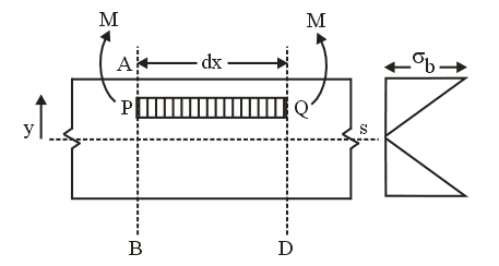
Shear force and bending moment diagram problems and solutions pdf. Solution to Problem 404 | Shear and Moment Diagrams Tags: moment diagram shear diagram shear and moment diagrams simple beam concentrated load moment load. Problem 404 Beam loaded as shown in Fig. Sign Convention The customary sign conventions for shearing force and bending moment are represented by the figures below. Mechanics of Materials: Bending - Normal Stress » Mechanics of... Shear and Moment Diagrams. Transverse loading refers to forces that are perpendicular to a structure's long axis. These transverse loads will cause a bending moment M that induces a normal stress, and a shear force V that induces a shear stress. PDF CHAPTER | Normal Force, Shear Force, Bending Moment and Torsion It is convenient to consider shear force and bending moment distributions in beams simultaneously since, as we shall see in Section 3.5, they are Again the method of construction of shear force and bending moment diagrams will be illustrated by examples. Example 3.4 Cantilever beam with a... Shear Force and Bending Moment Diagram Strength of Material ...Moment Diagram is topic-wise collection of Important notes, Topic Wise tests, Video lectures, NCERT Textbook, NCERT Solution, and Previous Year papers is EduRev is providing videos for important topics in Shear Force and Bending Moment Diagram for Mechanical Engineering.
How to draw shear force and bending moment diagrams... - Quora Bending Moment and Shear Force Diagram Calculator. Edit: In the above tutorial for bending moment calculation length of the beam is assumed to I use a very good method to draw shear force and bending moment diagram but this method requires a good knowledge of reading graphs and... PDF Figure 1. Internal shear force and bending moment diagrams for... These internal shear forces and bending moments cause longitudinal axial stresses and shear. stresses in the cross-section as shown in the Figure 2 below. Step II. Calculate Lb and Cb for the laterally unsupported spans. Since this is a symmetric problem, need to consider only span AB. PDF Structural Analysis III | Chapter 5 - The Moment-Area Method Part (a) - Reactions and Bending Moment Diagram Reactions Taking the whole frame, and showing the calculated value for R, we have Problem 5 For the following prismatic frame, find the bending moment and shear force diagrams and the horizontal and vertical deflections at D. Take EI... Mechanics of Materials Chapter 4 Shear and Moment In Beams The shear force and bending moment diagrams are convenient visual references to the internal forces in a beam; in particular, they identify the maximum values ...42 pages
Pset #5 Solutions 3.11 Fall 2003 Solution Problem #1 We have determined the expressions for the shear forces and bending moments in the beam, and have made accompanying shear force and bending moment diagrams.18 pages How to Calculate and Draw Shear and Bending Moment Diagrams To complete a shear force and bending moment diagram neatly you will need the following You have finished calculating and drawing shear and bending moment diagrams as well as an This will help you become better at calculating all typed of these problems, and you will certainly be ahead of... 5.0 Drawing Shear Force and Bending Moment Diagrams - An... This is a problem. Without understanding the shear forces and bending moments developed in a structure you can't complete a design. Shear force and bending moment diagrams tell us about the underlying state of stress in the structure. So naturally they're the starting point in any design process. PDF Microsoft Word - Chapter07.doc shear forces cause transverse shear-stress distribution through the beam cross section as shown in. Although this is violated when the beam is subjected to both bending and shear, we can generally Look at a FBD of the element dx with the bending moment stress distribution only, Fig.
Solved For the beam and loading shown below, by using the ...
PDF 95.7.2 V and M Diag Intro | Find Shear and Bending Moment Diagrams Recall the Internal Force Example Problem. A beam is supported by a pin support at point A and extends over a roller support at point D. The beam General procedure for the Construction of Shear and Bending Moment Diagrams. 1. Find all of the external forces (support reactions); 2. Choose a...

Book Solution) 6-2, Mechanics of Materials by R C Hibbeler ...
(PDF) Chapter 5 Bending Moments and Shear Force Diagrams for... 5.0 SHEAR FORCE AND BENDING MOMENTS DIAGRAMS FOR BEAMS A Shear Force Diagram (SFD)indicates how a force applied perpendicular to 5.1 Beam shear force and bending moment sign convention Where distributed load acts downward on the beam; internal shear force causes a...
Solution to Problem 403 | Shear and Moment Diagrams ...
Shear and moment diagram - Wikipedia Shear and bending moment diagrams are analytical tools used in conjunction with structural analysis to help perform structural design by determining the value of shear force and bending moment at a given point of a structural element such as a beam.
DE-12: Lesson 19. SOLVED EXAMPLES BASED ON SHEAR FORCE AND ...
PDF Microsoft Word - Chapter 10-98.doc the shear force and bending moment diagrams can be plotted. thus the slope and deflection equations are. force P acting at point D determine reactions at the ends also determine D. this is a 2-degree of indeterminacy problem. select MA and MB as the redundants.

moment d'une force
Drawing Bending Moment Diagrams Effectively - MechanicalBase Inclined distributed shear force and shear force/bending moment diagrams(Image Source:D. K. Singh - Strength of Materials-Springer, 2020 If you understand the general logic of obtaining bending moment and shear force diagrams, you will able to solve all the problems related to this...

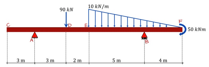
Solved) - Determine the reactions and draw the shear and ...
Module -4 Shear Force and Bending Moment Diagrams Shear Force and Bending Moment Diagrams. Syllabus. Introduction, Types of beams, loads and reactions, shear forces and bending moments, rate of.12 pages
Analysis of Beams | Shear Force & Bending Moment Diagram
Shear Force & Bending Moment Diagram of Simply Supported Beam Shear force and bending moment diagram of simply supported beam can be drawn by first calculating value of shear force and bending moment. Shear force and bending moment values are calculated at supports and at points where load varies.
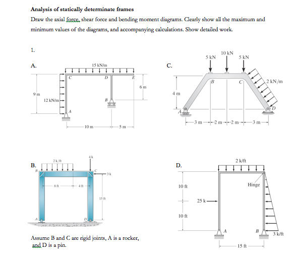
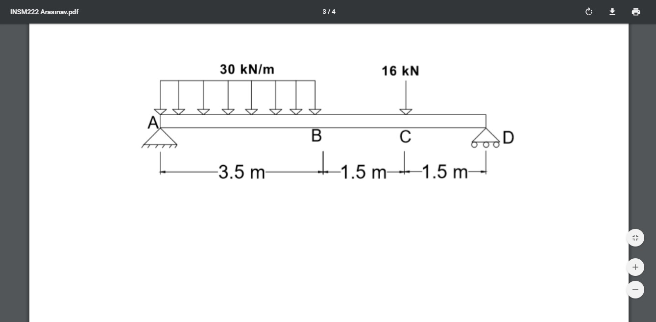
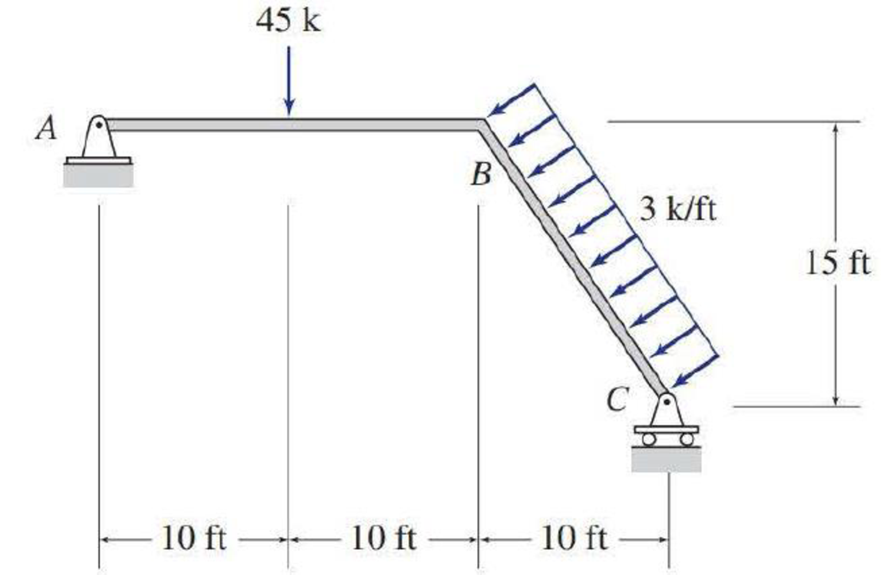
Solved) - Analysis of statically determinate frames Draw the ...
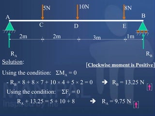
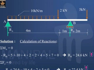
Civil Engineering - Solved Examples for shear force and bending... collection of solved problems and examples in civil engineering, Solution of selected problems on Shear force and bending moment diagrams. All the steps of these examples are very nicely explained along with SFD and BMD and will help the students to develop their problem solving skills.

MECHANICS OF MATERIALS Pages 151-200 - Flip PDF Download ...
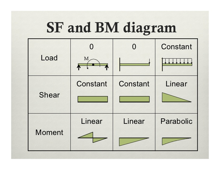
Beams – SFD and BMD Shear and Moment Relationships ... Slope of the moment curve = Shear Force ... Draw the shear and bending moment diagrams for the beam and loading shown.21 pages
Shear force and bending moment diagram
Shear Forces and Bending Moments 264 CHAPTER 4 Shear Forces and Bending Moments. Problem 4.3-9 A curved bar ABC is subjected to loads in the form of two equal and opposite forces Problem 4.5-3 Draw the shear-force and bending-moment diagrams for a cantilever beam AB carrying a uniform load of intensity q over...
Mechanics of Materials Chapter 4 Shear and Moment In Beams
PDF Stresses: Beams in Bending | force in the axial direction be zero, i.e. Construct the shear-force and bending-moment diagrams, noting in partic-ular the location of the maximum bending moment. Equivalence of this normal stress distribution sketched below to zero resultant force and a couple equal to the bend-ing moment at any station along the span proceeds...
Shear force and bending moment of beams
Bending Moment & shear force - NPTEL Problem 6: Bending Moment Diagram Plot shear and bending-moment diagrams for a simply supported beam with a uniformly distributed load; see Solution: Concept: A hinge can transfer axial force and shear force but not bending moment. So, bending moment at the hinge location is zero.
DE-12: Lesson 19. SOLVED EXAMPLES BASED ON SHEAR FORCE AND ...
PDF IntroReview 2. Draw the axial force, shear force and bending moment diagram for member AE. Deflected shape. IntroReview Page 3. Final Problem Statement of Structural Analysis. Note: • For most practical problems, analytical (exact) solutions to the above system of PDEs, are not possible to obtain. •

4.5 Practice Problems | Learn About Structures
Shear Force and Bending Moment Diagrams - Wikiversity Hence bending moment is shown on a bending moment diagram. The same case from before will be used here To make your life more difficult I have added an external force at point C, and a point moment to the diagram below. This is the most difficult type of question I can think of, and I will do...
Bending ,Shear and Combined Stresses Study Notes for ...
PDF How to find Bending Moment | Shear Force Diagram > BMD Bending moment is a torque applied to each side of the beam if it was cut in two - anywhere along its length. The hinge applies a clockwise (+) moment (torque) Shear Force is in all beams, but usually only seen as a problem in SHORT beams. Long beams fail by bending. Bending-Moment Page 5.

PDF) Shear Forces and Bending Moments | Naidu Dogga and Md ...
PDF STRUCTURAL ANALYSIS | Shear and Bending Moment Diagrams Axial Force, Shear Force and Bending Moment. Diagrams for Plane Frames. Previous definitions developed for shear forces and bending moments Statically Determinate ≡ the bending moments, shears, and axial forces in all its members, as well as the external reactions, can be determined by...

4.5 Practice Problems | Learn About Structures
CHAPTER 2 Shear Force And Bending Moment - PDF4PRO The force that results in bending is known as bending moment. - Draw the shear force and bending moment diagrams. SHEAR FORCE & BENDING MOMENT ...77 pages
Why I find the shear force digram and bending moment diagram ...
PDF Design Aid 6 Beam Design Formulas with Shear and Moment Diagrams Shear and moment diagrams and formulas are excerpted from the Western Woods Use Book, 4th edition, and are provided herein as a courtesy of Western Wood Products Association. E = modulus of elasticity, psi I = moment of inertia, in.4 L = span length of the bending member, ft.
Mechanics of Materials Chapter 4 Shear and Moment In Beams
Shear and Moment Diagrams Ambrose - Chapter 6 [10] shear force diagram & bending moment diagram. Syahrir Qoim. 6161103 7.2 shear and moment equations and diagrams. Shear Force And Bending Moment In Beams.
Shear force and bending moment diagram practice problem #4
PDF Structural Engineering II Example Draw the axial force, shear force and bending moment diagrams of the frames loaded as shown below. Bending Moment and Shear Force from Approximate Analysis Based on the approximations mentioned (i.e., points of Solutions for Problems on Flexibility Method for Trusses.
Shear force and bending moment diagram practice problem #8
Bending Moment & shear force
Draw the shear, bending moment, and axial force diagrams and ...
The Ultimate Guide to Shear and Moment Diagrams ...
![Solved] The slope of Bending moment diagram at any section of ...](https://storage.googleapis.com/tb-img/production/17/11/04.11.2017.021.JPG)
Solved] The slope of Bending moment diagram at any section of ...
Structural Axial, Shear and Bending Moments
STRUCTURAL ANALYSIS

PDF) 7 Solutions 44918 | Adriano Cruz - Academia.edu

Shear Forces and Bending Moments
Problem 9.1 Two beam segments, AC and CD, are connected ...

18 Structural Formulas ideas | structural formula, bending ...

6 Le moment d 'une force
Shear force and bending moment diagram

Shear force and bending moment diagram practice problem #1
4. Bending Moment and Shear Force Diagram
Module -4 Shear Force and Bending Moment Diagrams
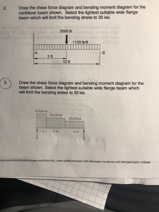
Solved 2. Draw the shear force diagram and bending moment ...
0 Response to "37 shear force and bending moment diagram problems and solutions pdf"
Post a Comment