38 grasslin timer wiring diagram
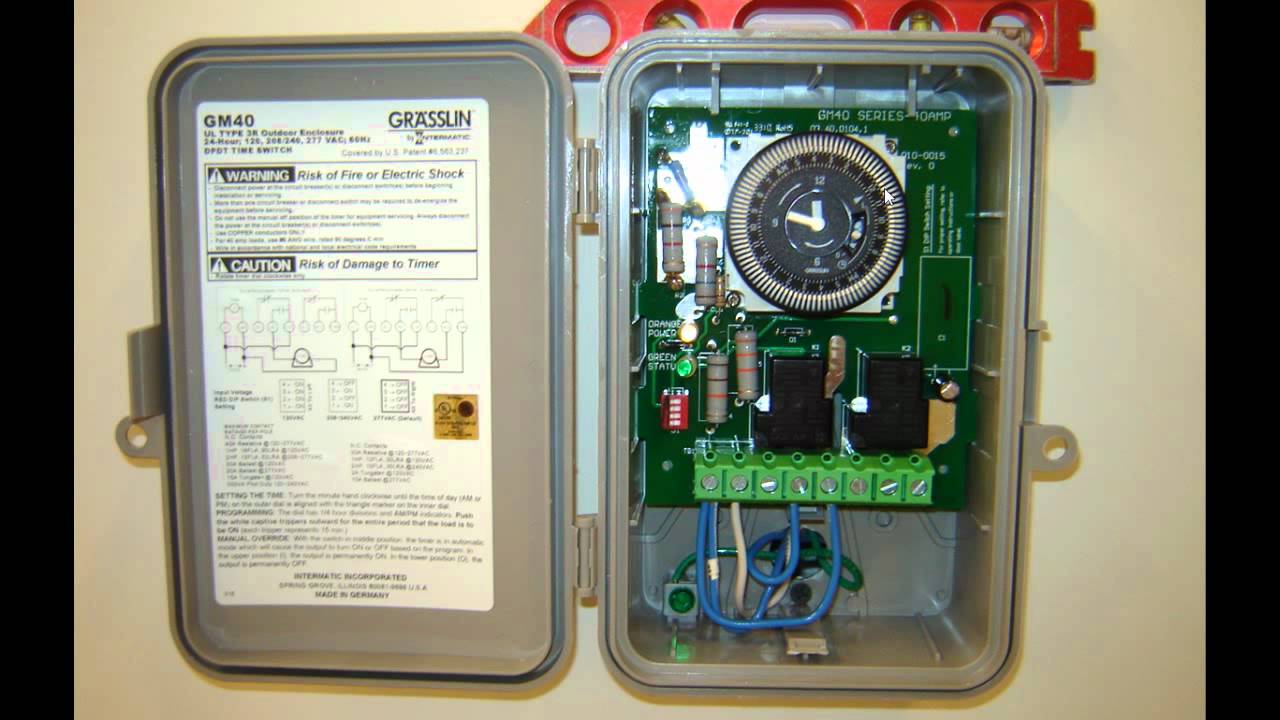
Defrost Timer Controls / HVAC/R - Neuco Type 1 Enclosure Dimensions. Wiring diagrams in powered refrigeration mode. Note: Equivalent in function, terminal identification, and wiring allows for quick.8 pages GM40 General Purpose Multi-Voltage Commercial Time Switch Remove timer mechanism by releasing spring clip on bottom. ... Wire in accordance with National and Local Codes (see wiring diagrams).4 pages
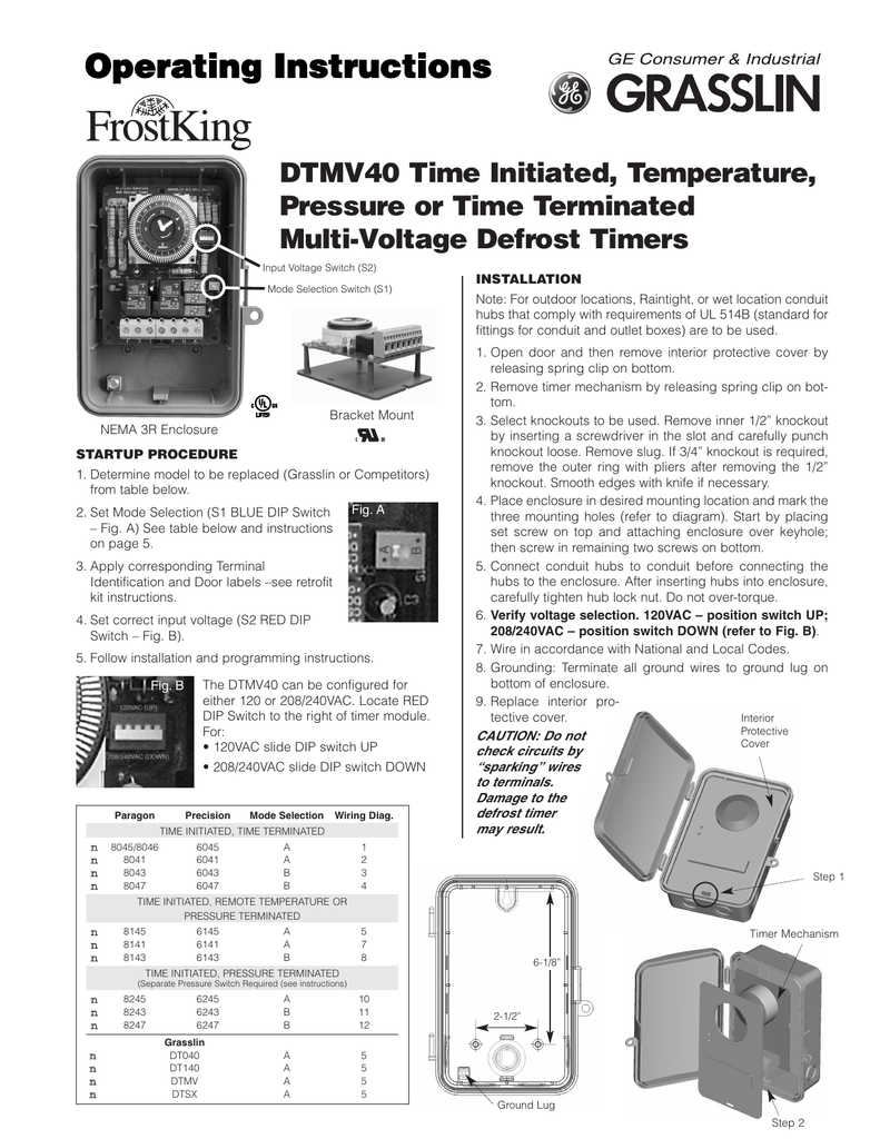
DTMV40 Time Initiated, Temperature, Pressure or Time ... See wiring diagrams 8 & 9. 8240/6240 SERIES REPLACEMENT: The DTMV40 may be used to replace the Paragon 8240 or Precision 6240 series defrost timers with ...7 pages
Grasslin timer wiring diagram
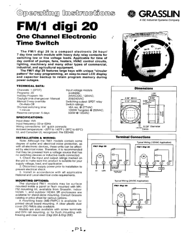
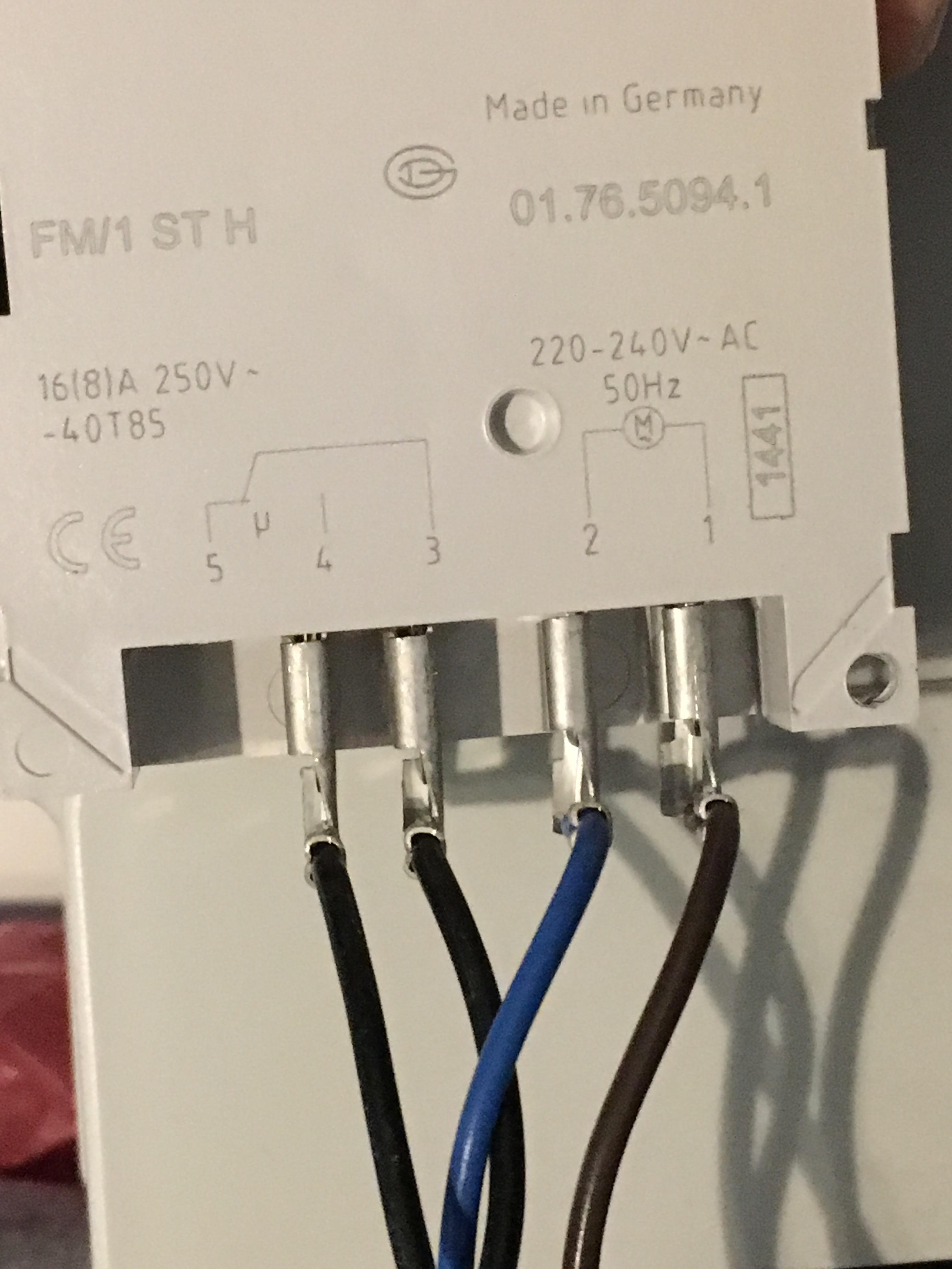
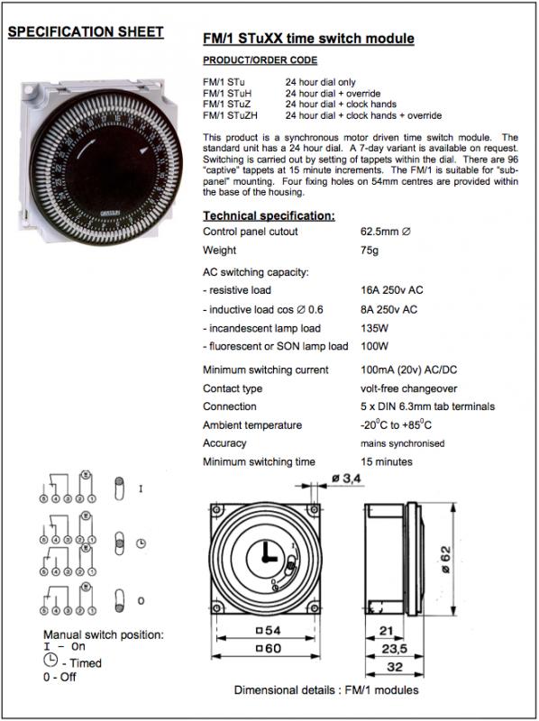
Socket box timer The diagram shows wiring for a mains-operated load. The link between terminals. 3 and 5 must be fitted by the installer. For low voltage switching connect 230V ...4 pages Installation & Operating Instructions - Rogers Supply proper position from table below and wiring diagrams indicated. ... Series or Precision 6040, 6140 Series and all prior Grasslin Defrost Timer models.12 pages Print Grasslin Time Clock Operating Instructions.tif (4 pages) GRASSLIN. Operating Instructions. FM/1 digi 20 ... Wiring connections: 1/4" quick connects ... The timer cannot be programmed unless.4 pages
Grasslin timer wiring diagram. Print Grasslin Time Clock Operating Instructions.tif (4 pages) GRASSLIN. Operating Instructions. FM/1 digi 20 ... Wiring connections: 1/4" quick connects ... The timer cannot be programmed unless.4 pages Installation & Operating Instructions - Rogers Supply proper position from table below and wiring diagrams indicated. ... Series or Precision 6040, 6140 Series and all prior Grasslin Defrost Timer models.12 pages Socket box timer The diagram shows wiring for a mains-operated load. The link between terminals. 3 and 5 must be fitted by the installer. For low voltage switching connect 230V ...4 pages
GM 40 Time Clock
Combi boiler timer wiring help | DIYnot Forums
Operating Instructions

Electrical Engineering Topics: March 2021

How to wire GM40 GM40AV GM40AVE WHQ series
FM1D14 Series 24-Hour/7-Day Time Switch Operation and User ...
SECTION - GRASSLIN
Analogues DIN rail time switches - talento 211

Grasslin Timer | eBay

Grasslin DTAV40 Auto Voltage Defrost Timer 120/240VAC Heatcraft Frost King

BA EQ7 (GB) - graesslin.de

Gate Loop Kit – Vandgard® - Anti Climb Guards Ltd

Am changing my diehl 880 timer for a grasslin - Fixya
Bubble Grasslin Time Clock Operating Instructions | Manualzz

TFC Group Grasslin SB-Digi+ 24/7 Digital Socket Box ...
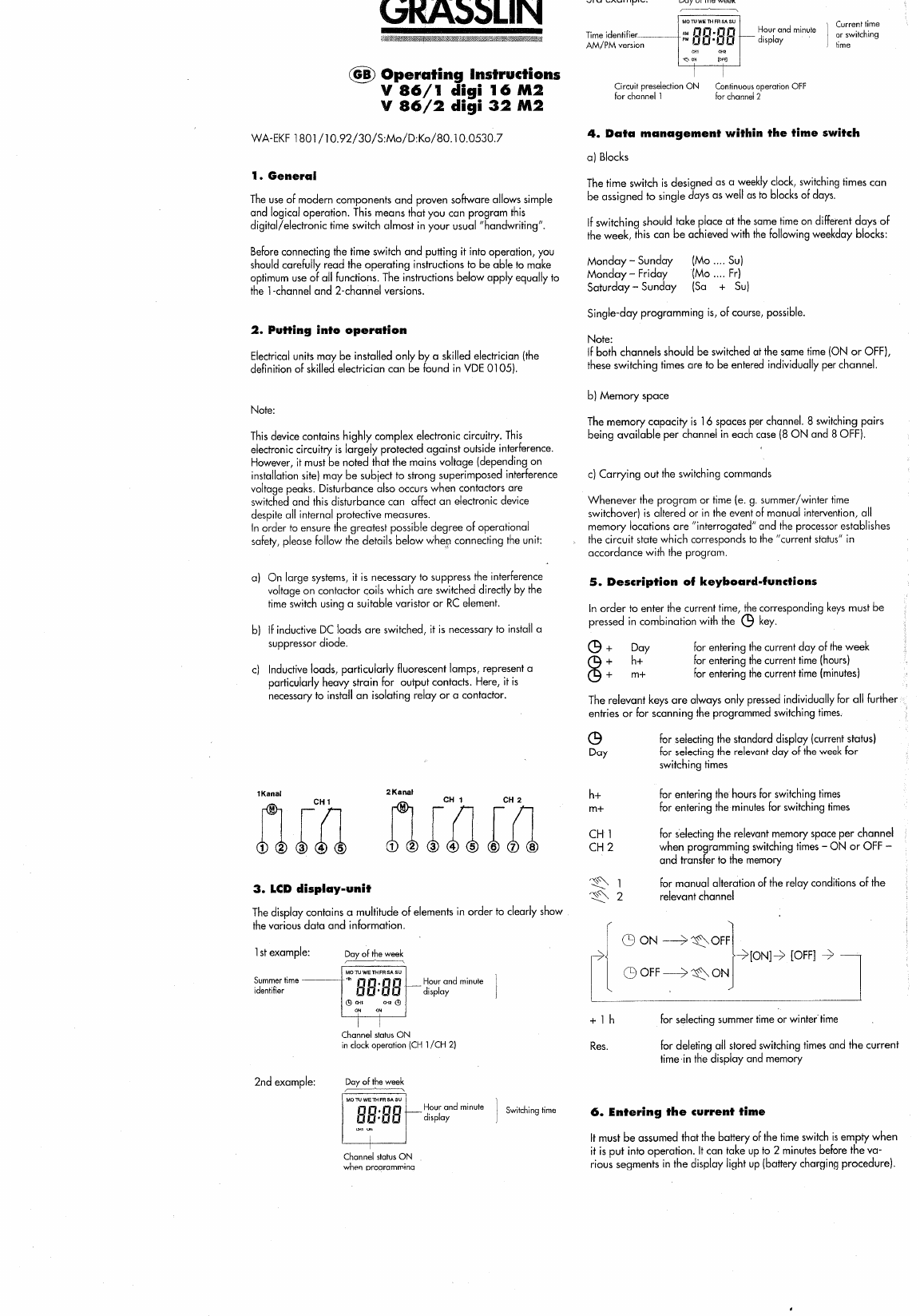
Manual Grasslin V86-2 digi 32 M2 (page 1 of 2) (English)
PF1103T-wiring-diagram.gif | Trouble Free Pool
Multi-Voltage Defrost Timer
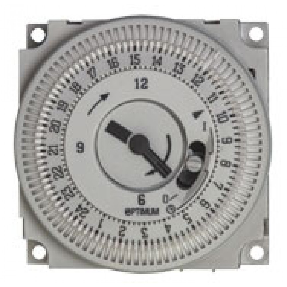
Mechanical Timer for Combi Boilers

Streamline Defrost Timer Installations With Intermatic's ...

GRASSLIN 120/208 DEFROST TIMER

I just fitted a grasslin socket box timer for my oil heating ...
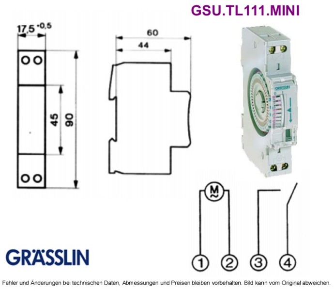
Verteilerschaltuhr synchron talento 111 mini, Grieder ...

Wiring the timer clock on a grasslin talento 111 for my pool ...
MIL 72 O.I.
WARNING Risk of Fire or Electric Shock CAUTION Risk of Damage ...
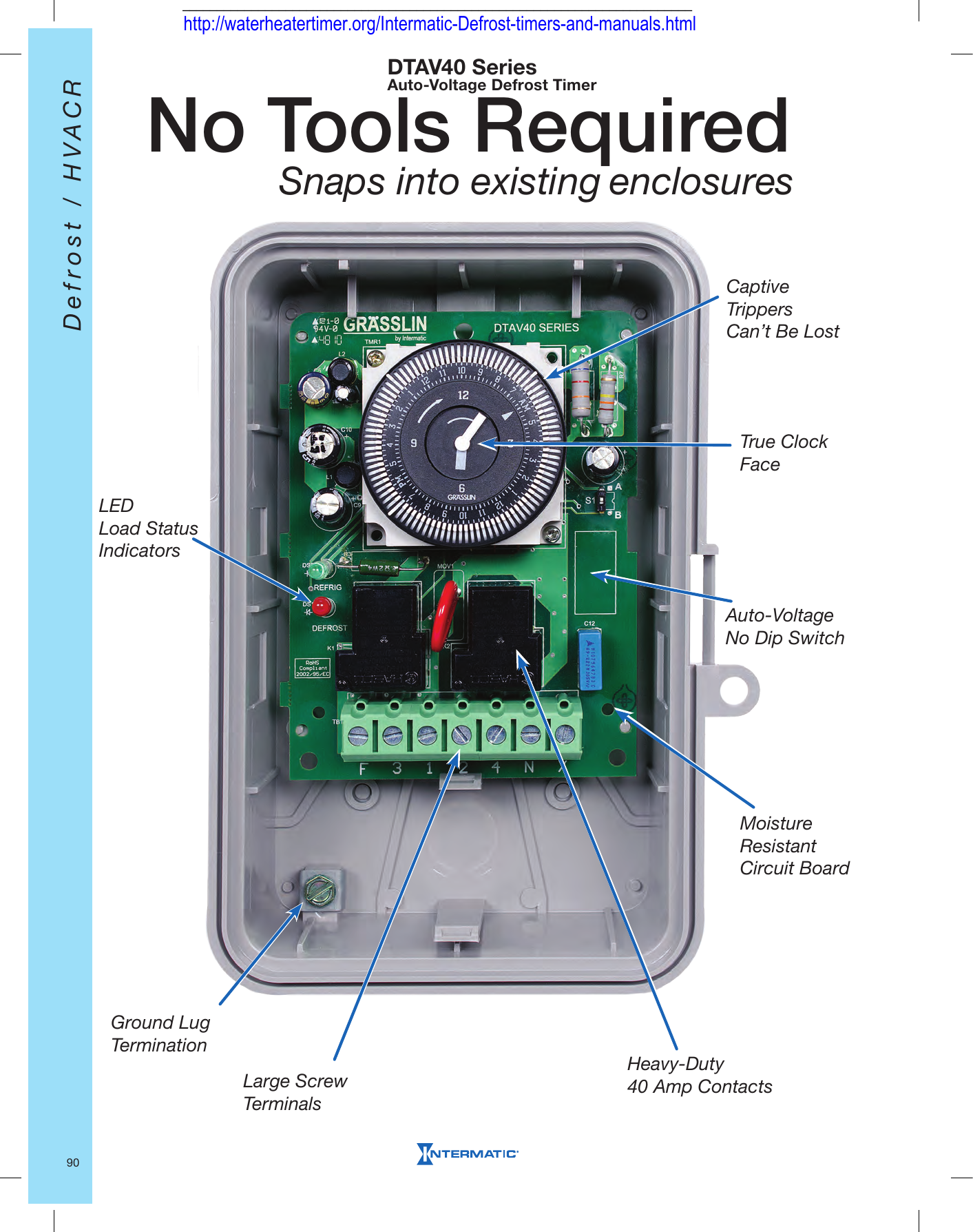
No Tools Required Snaps into existing enclosures

tee 1 uni com timer Questions & Answers (with Pictures) - Fixya
GRASSLIN CONTROLS CORPORATION ON/OFF Switch must always be "ON"!
Mechanical Timer Switch - Boilers & Hot Water Tanks ...
Replacing analogue timer help please | DIYnot Forums
Untitled

Timer modules
Neue Lautsprecher für's ROLAND FR-8X | Musiker-Board

Grasslin by Intermatic FM1STUZH-120U 24-Hour 21A, SPDT, 120V Electromechanical Timer Module with Manual Override Switch
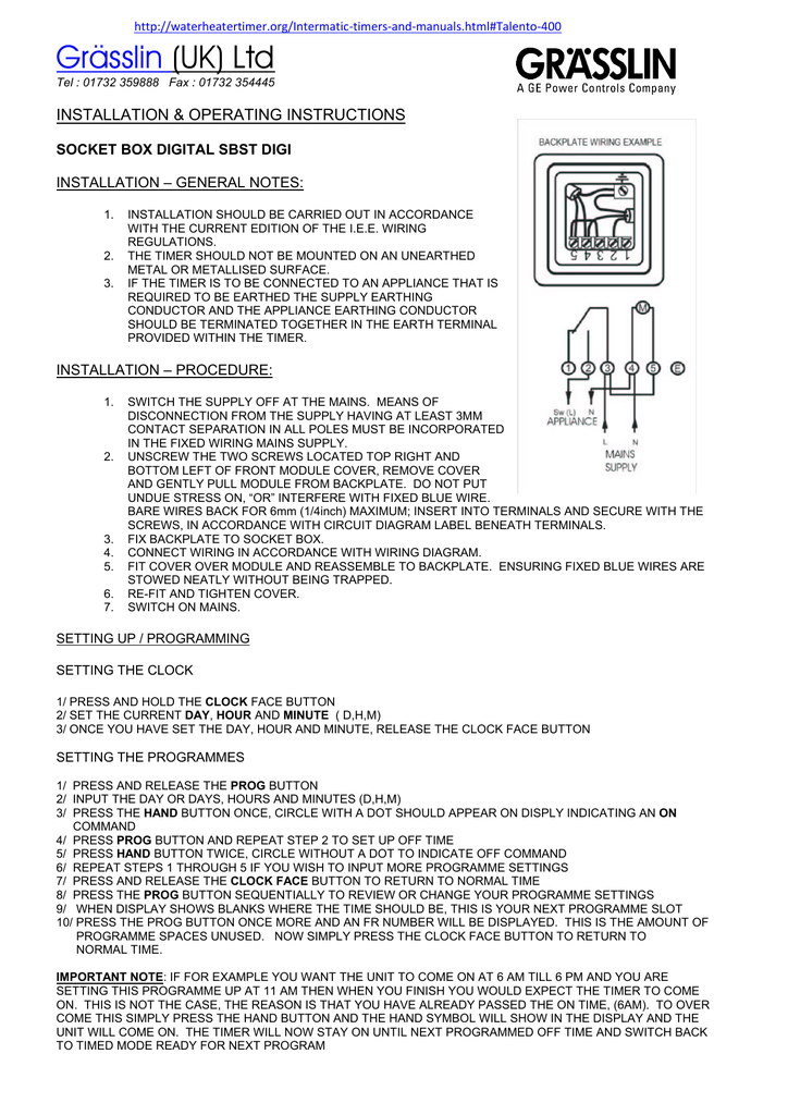
Grässlin (UK) Ltd INSTALLATION & OPERATING INSTRUCTIONS

Grasslin QEG-1 Operating Manual | Manualzz
Connecting Nest To A Baxi 80E Boiler Which Has Grasslin Timer ...
0 Response to "38 grasslin timer wiring diagram"
Post a Comment