41 iron nickel phase diagram
Figure 2.6: The iron-nickel phase diagram, which includes terminology describing meteorites of specific Ni concentrations. i.e. a medium octahedrite is an iron meteorite which contains 6.5 - 10.5 Ni wt %. Also, this figure shows the nickel percentages often found associated with Fe-ni phase diagram Alpha and gamma solubility limits in iron-nickel phase diagram at high temperatures - quench- and-anneal and diffusion couple techniques and electron probe microanalysis. Document ID. 19650020214. Document Type. Technical Memorandum (TM) Authors. Goldstein, J. I. (NASA Goddard Space Flight Center Greenbelt, MD, United States)
Iron--Nickel--Tungsten Phase Diagram. F. Winslow Published 1971 Materials Science In support of a study of the properties of liquid-phase-sintered iron-nickel-tungsten alloys, the most probable phase diagram was drawn. The space diagram is shown as a series of isothermal sections between 1,650 and 800° C and a liquidus and solidus projection.
Iron nickel phase diagram
Jun 01, 1991 · These changes are also applicable to this table as printed in “Fe-Ni (Iron-Nickel)” in Phase Diagrams of Binary NickelAlloys, P. Nash, Ed., ASM International (1991). The correct table is printed in this evaluation in Phase Diagrams of Binary lron Alloys, H. Okamoto, Ed., ASM International, to be published (1993). testing and metallographic evaluation. A time-temperature-hardness diagram was prepared for each iron, nickel, and cobalt combination. Scanning electron microscopy was performed to document microstructural features while phase identification was performed using X-ray diffraction and energy @article{osti_20002039, title = {Pourbaix diagrams for the ternary system of iron-chromium-nickel}, author = {Beverskog, B and Puigdomenech, I}, abstractNote = {Pourbaix diagrams (potential-pH diagrams) for the ternary system of Fe-Cr-Ni at 25 C to 300 C were calculated. Extrapolation of thermochemical data to elevated temperatures was performed with the revised model of Helgeson-Kirkham ...
Iron nickel phase diagram. Addendum. In Vol. 12, No. 3, page 301 ("The Fe-Ni (Iron-Nickel) System," by L.J. Swartzendruber, V.R Itkin, and C.B. Alcock), in Table 6 three. figures contained incorrectly placed decimal points ... This document is part of Volume 11 `Ternary Alloy Systems: Phase Diagrams, Crystallographic and Thermodynamic Data', Subvolume D `Iron Systems', of Landolt-Börnstein - Group IV `Physical Chemistry'. At this temperature, iron is partitioned to the β and transient pyrrhotite phase, which has only a small temperature range of stability before the emergence of pentlandite. Not obvious in these plots but evident in the copper-nickel phase diagram is a tendency to immiscibility in the fcc phase at low temperatures. Phase Diagrams • Indicate phases as function of T, Co, and P. • For this course:-binary systems: just 2 components.-independent variables: T and Co (P = 1 atm is almost always used). • Phase Diagram for Cu-Ni system Adapted from Fig. 9.3(a), Callister 7e. (Fig. 9.3(a) is adapted from Phase Diagrams of Binary Nickel Alloys , P. Nash
Iron--Nickel--Tungsten Phase Diagram. Showing 1-4 of 25 pages in this report. PDF Version Also Available for Download. Physical Description. 21 p. Creation Information. Winslow, F. R. January 1, 1971. Context ... The geometry of the temperature–composition phase diagram of iron–nickel alloys suggests that the hcp–fcc–liquid triple point is located at 10 to 20 wt.% Ni at the pressure of the inner core boundary. The fcc phase could crystallize depending on the nickel and silicon contents in the Earth's core, both of which are fcc stabilizer. Previous article The general result of the X-ray work is to confirm the phase diagram given by Merica (i93o), which is given in fig. 1. This shows the existence of two phase fields, one face-centred cubic stretching from pure nickel towards the iron end of the diagram, and the other body-centred. The iron-nickel-aluminitum ternary equilibrium diagram 355 cubic ... Iron-nickel (Fe-Ni) alloy is the most abundant component in the Earth's core [1]. The amount ofNi in the core is about 5.5wt%, on the basis of geochemical models [2]. The phase diagram and physical properties of Fe have been extensively studied [3]. Iron crystallizes in the bcc structure under ambient conditions, and it
osti.gov journal article: phase-diagram study of alloys in the iron-chromium-molybdenum-nickel system Figure 8.1: PT phase diagram for pure water Phase Diagram of Pure Iron • There are three separate and distinct solid phases: alpha (α) Fe, gamma (γ) Fe, and delta (δ) Fe. • There are also three triple points in the iron PT diagram where three different phases coexist: - liquid, vapor, and delta Iron - Vapor, delta iron and gamma iron ... I've tried asteroid mining at metal rich and icy rings and not getting any of the materials I need, I've tried srv mining on planets with a good iron percentage just to never see a blip on my radar. I'm completely stuck. I've spent so much time trying to find basic resources thar I feel like I'm doing something wrong. The primary phase of low-carbon or mild steel and most cast irons at room temperature is ferromagnetic α-Fe. It has a hardness of approximately 80 Brinell. The maximum solubility of carbon is about 0.02 wt% at 727 °C (1,341 °F) and 0.001% at 0 °C (32 °F). When it dissolves in iron, carbon atoms occupy interstitial "holes". Being about twice the diameter of the tetrahedral hole, the carbon ...
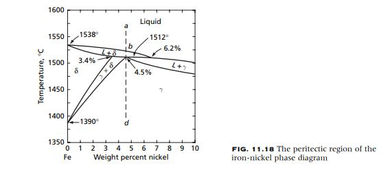
Solved 11.6 Consider the iron-nickel peritectic | Chegg.com
Cr-Fe-Ni (Chromium-Iron-Nickel) Cr-Fe-Ni (Chromium-Iron-Nickel) Raghavan, V. 2008-12-05 00:00:00 JPEDAV (2009) 30:94-95 Section II: Phase Diagram Evaluations DOI: 10.1007/s11669-008-9449-y 1547-7037 ASM International V. Raghavan The detailed review of the early results of the phase (a¢) phases. The Cr-Ni phase diagram [Massalski2] has a equilibria of this system by [1988Ray] presented ...
Size and Shape Effects on the Phase Diagrams of Nickel-Based ...
I am now confused. Could anyone please tell me the authentic A1,A2,A3,A4 and ACM temperature...? ( in celcius)
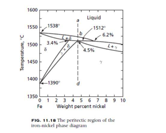
Solved What phases are in equilibrium at the peritectic ...
Section II: Phase Diagram Evaluations JPEDAV (2010) 31:184–185 DOI: 10.1007/s11669-010-9653-4 1547-7037 ÓASM International Fe-Ni-Si (Iron-Nickel-Silicon) V. Raghavan The review of this system by [1988Ray] presented a an ordered phase FeNi3 (L12, AuCu3-type cubic) forms tentative liquidus projection, partial isothermal sections at congruently from c.
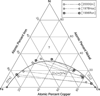
Cu-Fe-Ni (Copper-Iron-Nickel) | SpringerLink
The Cu-Ni phase diagram [ 2007Tur] depicts a continuous fcc solid solution between Cu and Ni. The solid solution breaks into Cu-rich and Ni-rich fcc phases at low temperatures. The Fe-Ni phase diagram [ 1991Swa] is characterized by a very narrow solidification range, with a peritectic reaction between (δFe) and liquid yielding (γFe).

Fe-Ni Phase Diagram and Database (GeDb for FactSage)
Schematic phase diagrams of iron-nickel system at the pressure of the inner core boundary. (a) If the Ni content in the outer core is less than that of the fcc-hcp-liquid triple point, the inner core could be composed of the hcp phase. (b) If the nickel content in the
Size and Shape Effects on the Phase Diagrams of Nickel-Based ...
We will limit our discussion of phase diagrams of multi-component systems to binary alloys and will assume pressure to be constant at one atmosphere. Phase diagrams for materials with more than two components are complex and difficult to represent. An example of a phase diagram for a ternary alloy is shown for a fixed T and P below.
![PDF] Iron--Nickel--Tungsten Phase Diagram. | Semantic Scholar](https://d3i71xaburhd42.cloudfront.net/edc9875279dacf5a2d776176d80c985c14c96fc5/17-Figure6-1.png)
PDF] Iron--Nickel--Tungsten Phase Diagram. | Semantic Scholar
Phase Diagram Resources from ASM International. Alloy phase diagrams and crystal structure data are used by metallurgists, materials engineers, and materials scientists to develop new alloys for specific applications; fabricate these alloys into useful configurations; design and control heat treatment procedures for alloys that will produce the required mechanical, physical, and chemical ...
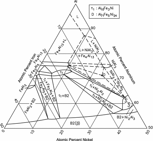
Al-Fe-Ni (Aluminum-Iron-Nickel) | SpringerLink
7.1. Al-Fe~Ni PHASE DIAGRAM This phase diagram can be used for the analysis of the phase composition of an 8001 alloy (Table 7.1) that contains only nickel and iron as the alloying elements. This phase diagram is also necessary for the analysis of more complex systems. In the Al-Fe-Ni ternary system, the AlsFe, AlsNi, and AIQECNI phases are
Chapter 8 Phase Diagrams
A. Phase Diagrams 1. Iron-Copper System The iron-copper phase diagram, taken from Hansen,3 is presented in Figure 1. Hansen3 also gives a thorough review of the work done on the system up to 1957. A review of more recent work, up to 1963 was done by . Elliott~ The most recent version of the phase diagram
![Fe-Ni phase diagram. [16] | Download Scientific Diagram](https://www.researchgate.net/profile/Rcs-Navarro/publication/286807012/figure/fig3/AS:587504373760005@1517083366669/Fe-Ni-phase-diagram-16_Q640.jpg)
Fe-Ni phase diagram. [16] | Download Scientific Diagram
[8] Compared to the phase diagram of pure Fe [Hemley and Mao, 2001], it is evident that the stability field of the fcc phase can be extended to higher pressures and lower temperatures with the addition of Ni (Figure 1). However, the effect of Ni on the phase diagram of Fe is not as dramatic as the addition of silicon in Fe [Lin et al., 2002].

Ternary phase diagram overview
At 1,500° C {Figure 4), a phase has appeared along the iron-tungsten side and iron rich gamma phase along the iron-nickel side, leading to two new tie triangles (a-Y-L and a-; -L). Points plotted from the vertical sections tie down the positions of the a-;-L and ~-W-L triangles, but the a-Y-L triangle is largely schematic. The tem
Chapter 8 Phase Diagrams
We have performed first-principles computation for the magnetic iron and iron-nickel over a wide range of pressure (0-400GPa) and temperature (0-6000K), within density-functional theory (DFT) in the generalized-gradient approximation using the projector augmented wave (PAW) method with the ABINIT code. We computed the free energies of hcp, bcc and fcc phases for iron and nickel including the ...

Binary Alloys - an overview | ScienceDirect Topics
Critical examination of the literature on the iron-nickel system indicates that the available phase diagram for the solid-state region is inadequate. The reason for this is that solid-state transformations in this system are mostly sluggish (particularly below 500°C) and classical equilibration-anneal methods using specimens from massive alloys are laborious and generally fall short of ...

File:Fe-Ni binary phase diagram.svg - Wikimedia Commons
Fe-Ni Phase Diagram u. T-r I. Guidstein and R. E. Ogilvie ABSTRACT The CY and y solubility limits in the Fe-Ni phase diagram have been redetermined at temperatures above 500OC. couple and a quench-and-annea technique were used. limits were measured with an electron probe microanalyzer. Both a diff'usion The solubility

Fe-rich section of iron-nickel phase diagram, redrawn after ...
For example, in the iron carbon phase diagram, addition of nickel lowers the A3 boundary while the addition of chromium raises it. Eutectic Point Eutectic point is a point where multiple phases meet. For the iron-carbon alloy diagram, the eutectic point is where the lines A1, A3 and ACM meet. The formation of these points is coincidental.

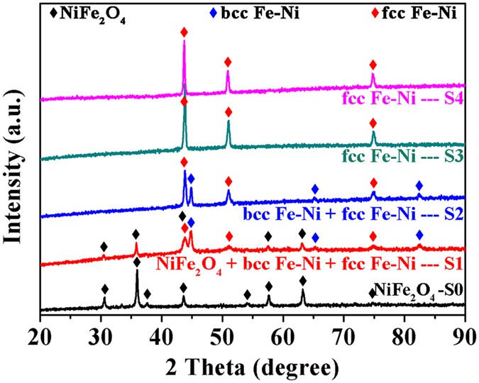
Individualized Pixel Synthesis and Characterization of ...
@article{osti_20002039, title = {Pourbaix diagrams for the ternary system of iron-chromium-nickel}, author = {Beverskog, B and Puigdomenech, I}, abstractNote = {Pourbaix diagrams (potential-pH diagrams) for the ternary system of Fe-Cr-Ni at 25 C to 300 C were calculated. Extrapolation of thermochemical data to elevated temperatures was performed with the revised model of Helgeson-Kirkham ...
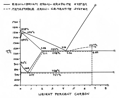
![Iron-Carbon Phase Diagram Explained [with Graphs]](https://fractory.com/wp-content/uploads/2020/03/Iron-carbon-phase-diagram-explained.jpg)
Iron-Carbon Phase Diagram Explained [with Graphs]
testing and metallographic evaluation. A time-temperature-hardness diagram was prepared for each iron, nickel, and cobalt combination. Scanning electron microscopy was performed to document microstructural features while phase identification was performed using X-ray diffraction and energy
Introduction - Microstructures - Cast Irons, High Alloy ...
Jun 01, 1991 · These changes are also applicable to this table as printed in “Fe-Ni (Iron-Nickel)” in Phase Diagrams of Binary NickelAlloys, P. Nash, Ed., ASM International (1991). The correct table is printed in this evaluation in Phase Diagrams of Binary lron Alloys, H. Okamoto, Ed., ASM International, to be published (1993).

Science of Alloying
Catalysts | Free Full-Text | Ni Promotion by Fe: What ...

Austenitic Steels :: Total Materia Article
![6 Phase diagram of Fe-Ni alloys ([8]) | Download Scientific ...](https://www.researchgate.net/profile/Ratchatee-Techapiesancharoenkij/publication/37598297/figure/fig4/AS:309877667844098@1450892001328/Phase-diagram-of-Fe-Ni-alloys-8.png)
6 Phase diagram of Fe-Ni alloys ([8]) | Download Scientific ...
Dependence of phase configurations, microstructures and ...
Nickel Based Superalloys

Magnetic phase diagram of the Fe–Ni system - ScienceDirect

Ni-Cr-Fe ternary phase diagram at 800 â—¦ C. The black solid ...
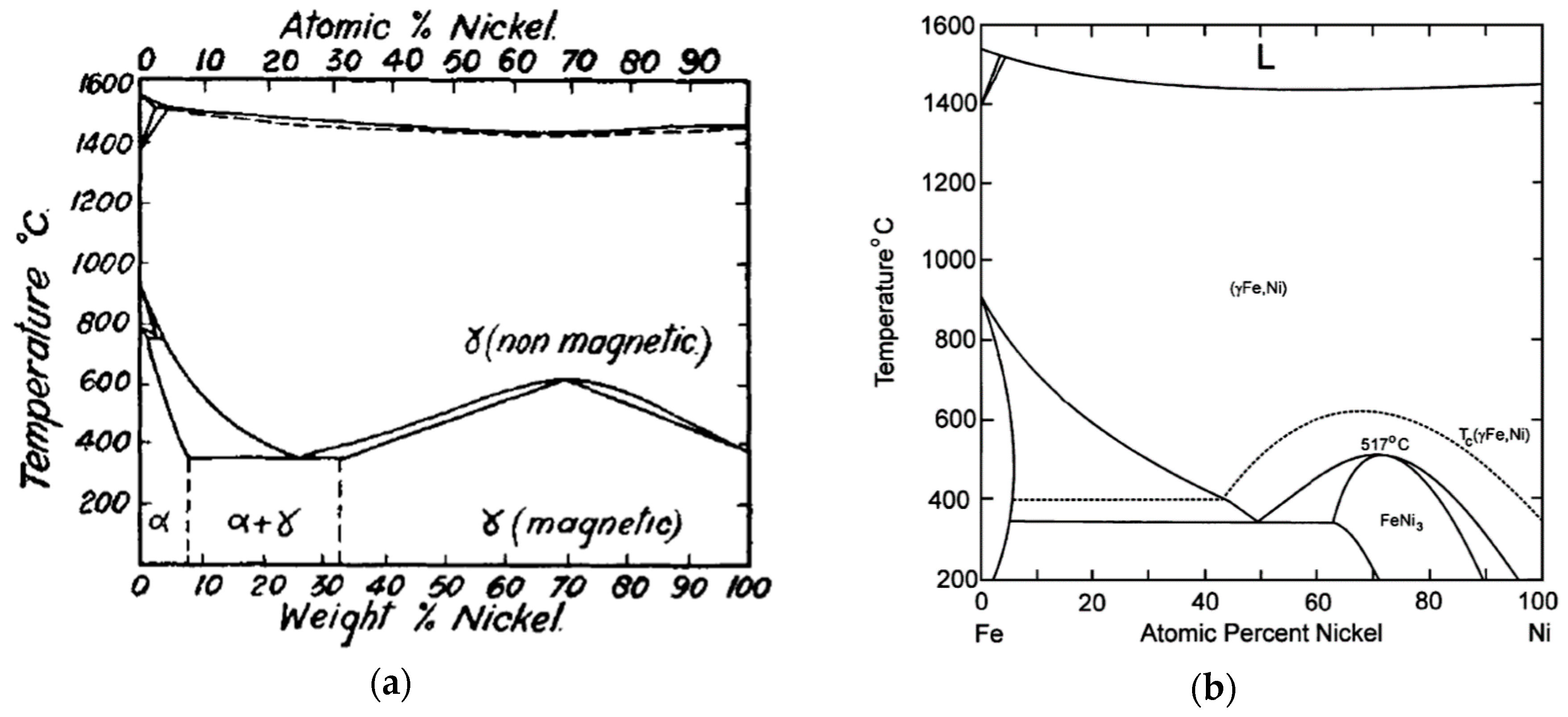
![Fe-Ni phase diagram [5,8] . | Download Scientific Diagram](https://www.researchgate.net/profile/Yuzeng-Chen-2/publication/253071558/figure/fig1/AS:392800127471616@1470662256947/Fe-Ni-phase-diagram-5-8.png)
Fe-Ni phase diagram [5,8] . | Download Scientific Diagram

Equilibrium phase diagram for Iron-Nickel-Chromium alloy ...

Allotropes of iron - Wikipedia
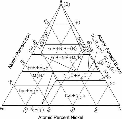
B-Fe-Ni (Boron-Iron-Nickel) | SpringerLink
![The Fe-Ni phase diagram from a literature [26]. | Download ...](https://www.researchgate.net/publication/272879847/figure/fig2/AS:615086280413192@1523659405670/The-Fe-Ni-phase-diagram-from-a-literature-26.png)
The Fe-Ni phase diagram from a literature [26]. | Download ...

Electroplating and characterization of cobalt–nickel–iron and ...
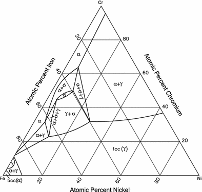
Cr-Fe-Ni (Chromium-Iron-Nickel) | SpringerLink
Teach Yourself Phase Diagrams and Phase Transformations
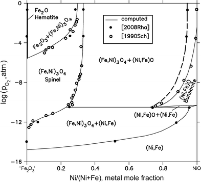
Fe-Ni-O (Iron-Nickel-Oxygen) | SpringerLink
![PDF] Iron--Nickel--Tungsten Phase Diagram. | Semantic Scholar](https://d3i71xaburhd42.cloudfront.net/edc9875279dacf5a2d776176d80c985c14c96fc5/15-Figure4-1.png)
PDF] Iron--Nickel--Tungsten Phase Diagram. | Semantic Scholar
![PDF] Iron--Nickel--Tungsten Phase Diagram. | Semantic Scholar](https://d3i71xaburhd42.cloudfront.net/edc9875279dacf5a2d776176d80c985c14c96fc5/14-Figure3-1.png)
PDF] Iron--Nickel--Tungsten Phase Diagram. | Semantic Scholar

Phase relations in the system Fe–Ni–Si to 200 GPa and 3900 K ...

The experimental phase diagram (left panel) shows the ...

Metallurgy

PDF) Fe-Ni-Si (Iron-Nickel-Silicon) | Vijayaraghavan ...
0 Response to "41 iron nickel phase diagram"
Post a Comment