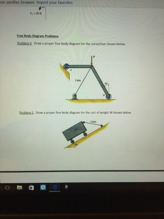
37 draw a proper free body diagram for the curved bar shown below.
PDF rpi.edu Created Date: 1/18/2011 11:30:55 AM Drawing Free-Body Diagrams - Physics Classroom Drawing Free-Body Diagrams. Free-body diagrams are diagrams used to show the relative magnitude and direction of all forces acting upon an object in a given situation. A free-body diagram is a special example of the vector diagrams that were discussed in an earlier unit. These diagrams will be used throughout our study of physics.
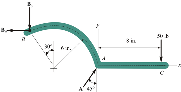
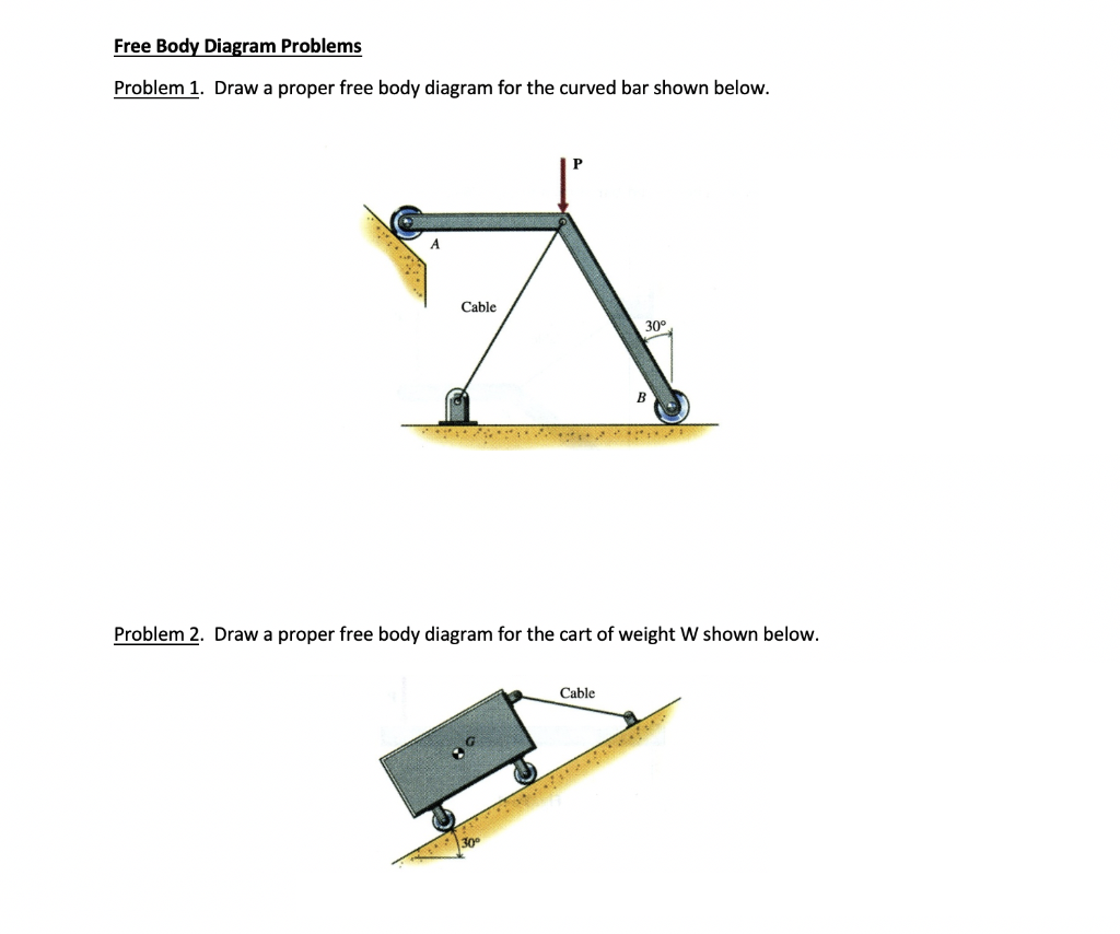
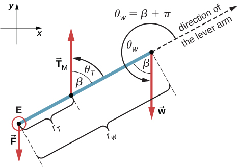
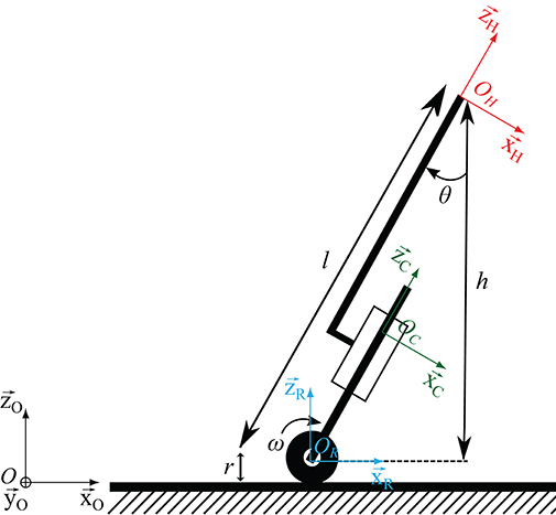
Free Body Diagrams and Particle Statics Problem 1. Draw a ... Draw a proper free body diagram for the curved bar AB shown below. Assume absence of friction in the problem. [15 points] Free body diagram with all external forces and necessary geometric entities = 15 points (Partial credit for missing components) Problem 2. Draw a proper free body diagram for the cart of weight W shown below.
Draw a proper free body diagram for the curved bar shown below.
Class 3 Notes - PROBLEM 2.46 Ropes AB and AC are thrown to ... Draw a proper free body diagram for the curved bar shown below. Q&A From 2 King 6:1-6, one of the disciples of Elisha was cutting a tree and the ax head fell into the water. Chapter 6 Drawing A Free-Body Diagram: Readings And ... Chapter 6 Drawing A Free-Body Diagram: Readings And Exercises. Course:Mechanics of material (MOM) T he free-body diagram is the most im-portant tool in this book. It is a drawing of a. system and the loads acting on it. Creating. a free-body diagram involves mentally sep- PDF Mechanical Engineering : University of Rochester Mechanical Engineering : University of Rochester
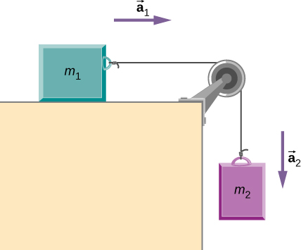
Draw a proper free body diagram for the curved bar shown below.. 5.7 Drawing Free-Body Diagrams - General Physics Using ... Figure 5.32 (a) The free-body diagram for isolated object A. (b) The free-body diagram for isolated object B. Comparing the two drawings, we see that friction acts in the opposite direction in the two figures. Because object A experiences a force that tends to pull it to the right, friction must act to the left. Because object B experiences a component of its weight that pulls it to the left ... homework 1 - ENGR 112 Spring 2016 Class 13 Statics 1 Free ... ENGR 112 - Spring 2016 - Class 13 Statics 1 Free Body Diagrams and Particle Statics Problem Set Free Body Diagram Problems Problem 1. Draw a proper free body diagram for the curved bar shown below. Problem 2. Draw a proper free body diagram for the cart of weight W shown below. [Solved] Draw the free-body diagram of the object. 30 ... Draw the free body diagrams of the two spur gears shown in Draw the free body diagrams of the two spur gears shown in Figure. Use the resulting equations of motion to show that T2 = NT1 if the gear inertias are negligible or if there is zero acceleration. Free Body Diagrams, Tutorials with Examples and Explanations Example 8 : A system with two blocks, an inclined plane and a pulley. A) free body diagram for block m 1 (left of figure below) 1) The weight W1 exerted by the earth on the box. 2) The normal force N. 3) The force of friction Fk. 4) The tension force T exerted by the string on the block m1. B) free body diagram of block m 2 (right of figure below)
5.7 Drawing Free-Body Diagrams - OpenStax Figure 5.32 (a) The free-body diagram for isolated object A. (b) The free-body diagram for isolated object B. Comparing the two drawings, we see that friction acts in the opposite direction in the two figures. Because object A experiences a force that tends to pull it to the right, friction must act to the left. Because object B experiences a component of its weight that pulls it to the left ... How to Draw a Free Body Diagram: 10 Steps (with Pictures) To draw a free body diagram, start by sketching a simple representation of the body you want to make the diagram of, like a square to represent a box. Next, draw arrows on the shape that show the forces acting on the object. For example, draw a downward arrow to signify the weight of the object, since gravity pulls the object down. What is a Free-Body Diagram and How to Draw it (with ... A free-body diagram is a representation of an object with all the forces that act on it. The external environment (other objects, the floor on which the object sits, etc.), as well as the forces that the object exerts on other objects, are omitted in a free-body diagram. Below you can see an example of a free-body diagram: [Solved] Draw the free-body diagram for a basketball ... Draw a proper free body diagram for the curved bar shown below. Draw the free body diagrams of the two spur gears shown in Use the resulting equations of motion to show that T2 = NT1 if the gear inertias are negligible or if there is zero acceleration.
› class › vectorsVector Addition - Physics Classroom Vector addition is one of the most common vector operations that a student of physics must master. When adding vectors, a head-to-tail method is employed. The head of the second vector is placed at the tail of the first vector and the head of the third vector is placed at the tail of the second vector; and so forth until all vectors have been added. [Solved] 12 K N/m CI D 1 m 21 24 K N/m 21 2 m A 2 m 1 m ... -Analyze completely the loaded frame shown below. The loadings are uniformly distributed load. Draw all free body diagrams (FBD) of members and joints with all notations properly labelled as used in your solution (analysis). E is constant for all members.-Determine the vertical and horizontal deflection at joint D using unit load method. 5.7 Drawing Free-Body Diagrams | University Physics Volume 1 Figure 5.32 (a) The free-body diagram for isolated object A. (b) The free-body diagram for isolated object B. Comparing the two drawings, we see that friction acts in the opposite direction in the two figures. Because object A experiences a force that tends to pull it to the right, friction must act to the left. Because object B experiences a component of its weight that pulls it to the left ... [Solved] Draw the free-body diagram for a person sitting ... Draw the free body diagrams of the two spur gears shown in Draw the free body diagrams of the two spur gears shown in Figure. Use the resulting equations of motion to show that T2 = NT1 if the gear inertias are negligible or if there is zero acceleration. Here T2 is taken to be the torque felt on shaft 2 due to the applied torque T1.
Modern mät- och övervakningsmetodik för bedömning av ...
Statics 1 Problem Set.docx - ENGR 216 - Summer 2020 ... ENGR 216 - Summer 2020- Statics Free Body Diagrams and Particle Statics Problem Set Free Body Diagram Problems Problem 1. Draw a proper free body diagram for the curved bar shown below. Problem 2. Draw a proper free body diagram for the cart of weight W shown below.
5.7 Drawing Free-Body Diagrams | University Physics Volume 1
DOC Things to Do Work Draw a free-body diagram of the entire truss (*shown below) ... Calculate the force needed to compress the steel bar shown below to Lo/2 if the bar is simultaneously heated up by 50oC (E=200GPa, L=12(10-6 /oC, Lo=0.5m, Ao=0.05m2). ... tensile stresses in the wall of a thin walled spherical pressure vessel tangential to the curved surface of the ...
Numerical methods for the modelling of chip formation
[Solved] Overheads will always be over-absorbed when A ... Draw a proper free body diagram for the curved bar shown below. Draw a proper free body diagram for the curved bar shown below. Previous Question. Next Question. Members. Access to 2 Million+ Textbook solutions; Ask any question from 24/7 available Tutors; $9.99.
Tutorial - A Complete Design Walkthrough with Altium Designer ...
essaysassignment.comEssays Assignment - One assignment at a time, we will help ... One assignment at a time, we will help make your academic journey smoother.
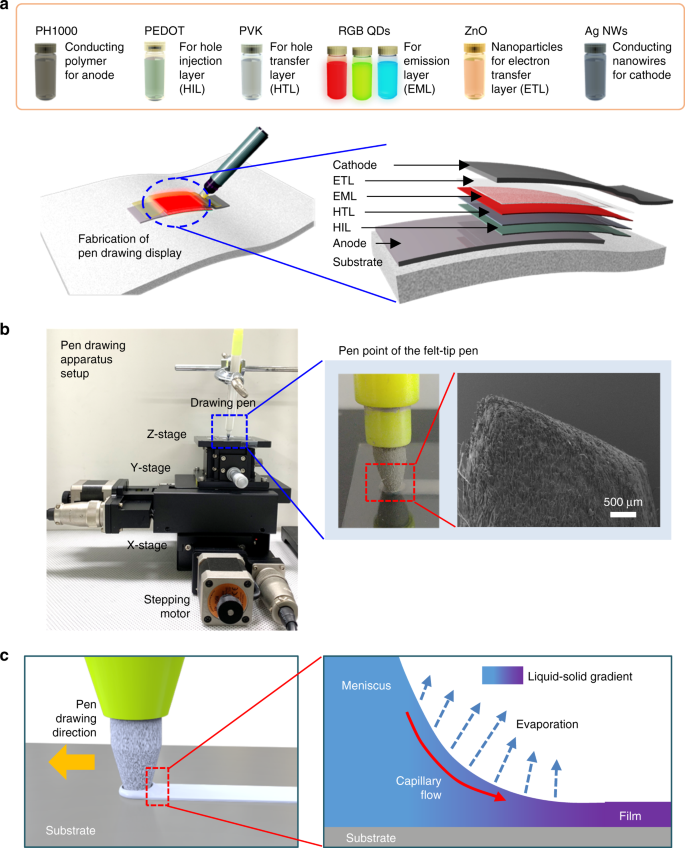
Pen drawing display | Nature Communications
PDF SOLUTION (Last) (First) the vertical deflection of end B of the beam. To this end, please follow the steps below: a) Draw a free body diagram (FBD) of the beam. From this FBD, write down the equilibrium equations for the beam. b) If the problem is indeterminate, choose the redundant load(s) on the beam, and write the remaining reactions in terms of the redundant load(s).
MANUAL ON STREAM GAUGING VOLUME 11 COMPUTATION OF DISCHARGE
Solved Free Body Diagram Problems Problem 1. Draw a proper ... Draw a proper free body diagram for the curved bar shown below. Problem 2. Draw a proper free body diagram for the cart of weight W shown below. Cable . This problem has been solved! See the answer See the answer See the answer done loading. Show transcribed image text Expert Answer.
![Solved] Draw the free-body diagram for a basketball player(a ...](https://s3.amazonaws.com/si.question.images/images/P-M-L-M(329).PNG)
Solved] Draw the free-body diagram for a basketball player(a ...
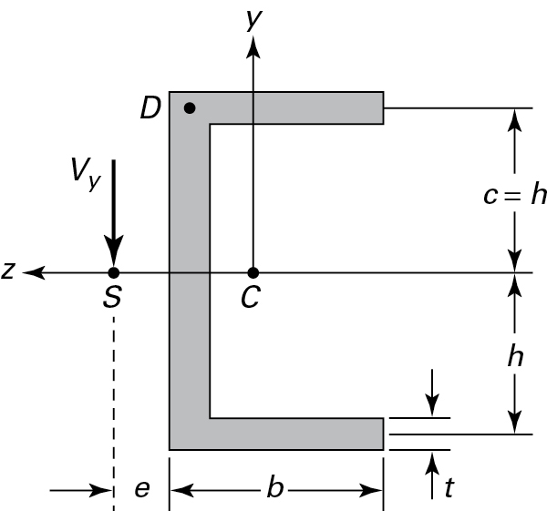
[Solved] Draw a proper free body diagram for the curved ... Draw free body diagram for the beam AB. 390 Ib 800 Ib A 3ft The steel curved bar shown has a rectangular cross section with a The radius of the centroidal axis is R = 40 mm.

Concrete plasticity—A historical perspective - Braestrup ...
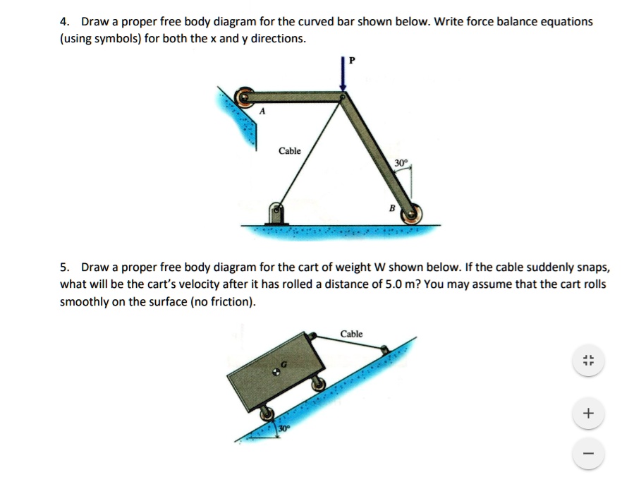
HW4_UAE_and_particlestatics.pdf - ENGR 216 ... - Course Hero (15 points) Draw a proper free body diagram for the curved bar shown below. Problem 7. (15 points) Draw a proper free body diagram for the cart of weight W shown below. Problem 8. (20 points).
Solved: Chapter 6 Problem 43P Solution | Engineering ...
PDF Lecture 13 FREE-BODY DIAGRAMS (Section 5.2) 2. Show all the external forces and couple moments. These typically include: a) applied loads, b) support reactions, and, c) the weight of the body. Idealized model. Free-body diagram (FBD) 1. Draw an outlined shape. Imagine the body to be isolated or cut "free" from its constraints and draw its outlined shape.

Ways of Engaging with Drawing | Emerald Insight
PDF Mechanical Engineering : University of Rochester Mechanical Engineering : University of Rochester
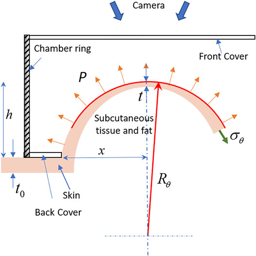
Frontiers | Non-Invasive in Vivo Quantification of ...
Chapter 6 Drawing A Free-Body Diagram: Readings And ... Chapter 6 Drawing A Free-Body Diagram: Readings And Exercises. Course:Mechanics of material (MOM) T he free-body diagram is the most im-portant tool in this book. It is a drawing of a. system and the loads acting on it. Creating. a free-body diagram involves mentally sep-

A three-dimensional approach to the Extended Limit Analysis ...
Class 3 Notes - PROBLEM 2.46 Ropes AB and AC are thrown to ... Draw a proper free body diagram for the curved bar shown below. Q&A From 2 King 6:1-6, one of the disciples of Elisha was cutting a tree and the ax head fell into the water.
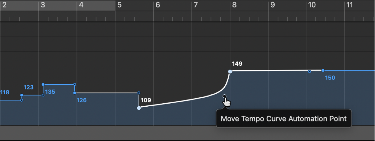
Create tempo curves in the Logic Pro Tempo track - Apple Support
Products - Recab - For demanding applications
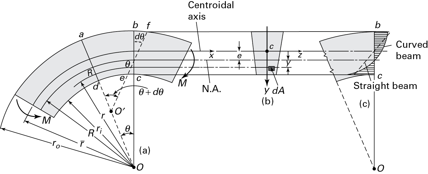
5.14 Curved Beam Formula | Bending of Beams | InformIT
5.7 Drawing Free-Body Diagrams | University Physics Volume 1

Hemodynamical analysis of MHD two phase blood flow through a ...
5.7 Drawing Free-Body Diagrams | University Physics Volume 1

Research on nonlinear, postbuckling and elasto-plastic ...
Dynamics (동역학) Lecture 6: Rigid Body Dynamics in 2D ...
Solved Free Body Diagram Problems Problem 1. Draw a proper ...
SOLVED:Draw proper free body diagram for the curved bar shown ...

Four-Bar Mechanism - an overview | ScienceDirect Topics

hw4.jpeg - Chenyan Feng, UIN: 32 700 45X) HW 4 Free Body ...
![Solved] Figure 4-49 shows a block (mass mA) on a smooth ...](https://s3.amazonaws.com/si.question.images/images/P-M-L-M(340).PNG)
Solved] Figure 4-49 shows a block (mass mA) on a smooth ...
Problems | Bending of Beams | InformIT
Solved Draw a proper free body diagram for the curved bar ...
Inclined Planes

Hinged Arch - an overview | ScienceDirect Topics
Surface roughness effect on fatigue strength of aluminum ...
12.2 Examples of Static Equilibrium – University Physics Volume 1
Frontiers | Robotic Cane Controlled to Adapt Automatically to ...

Scutoids are a geometrical solution to three-dimensional ...

To draw or not to draw: understanding the temporal ...
12.2 Examples of Static Equilibrium – University Physics Volume 1

How to Draw a Free Body Diagram - Simply Supported Beam with a Point Load
Design of Hollow Reinforced Concrete Columns in the Tubed ...
0 Response to "37 draw a proper free body diagram for the curved bar shown below."
Post a Comment