38 strobe light wiring diagram
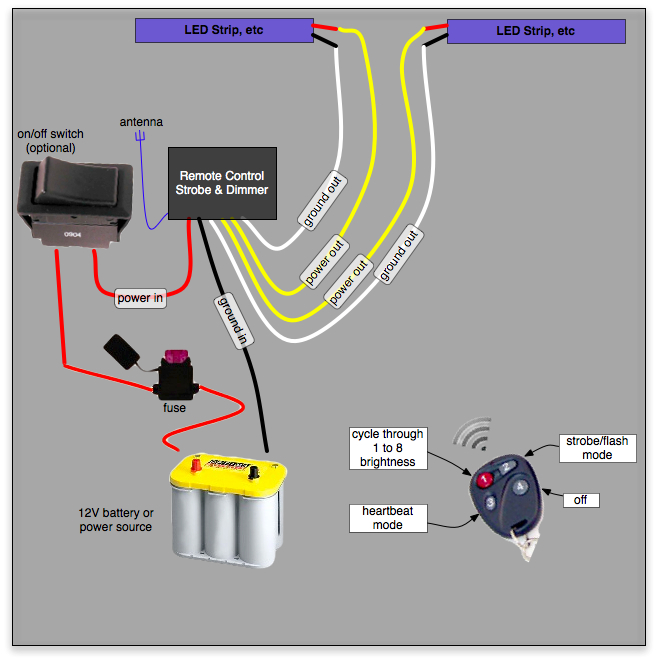
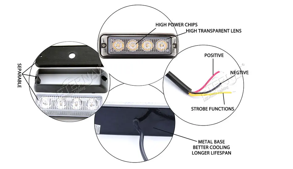
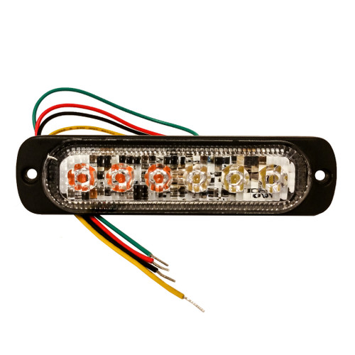
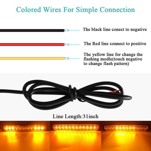
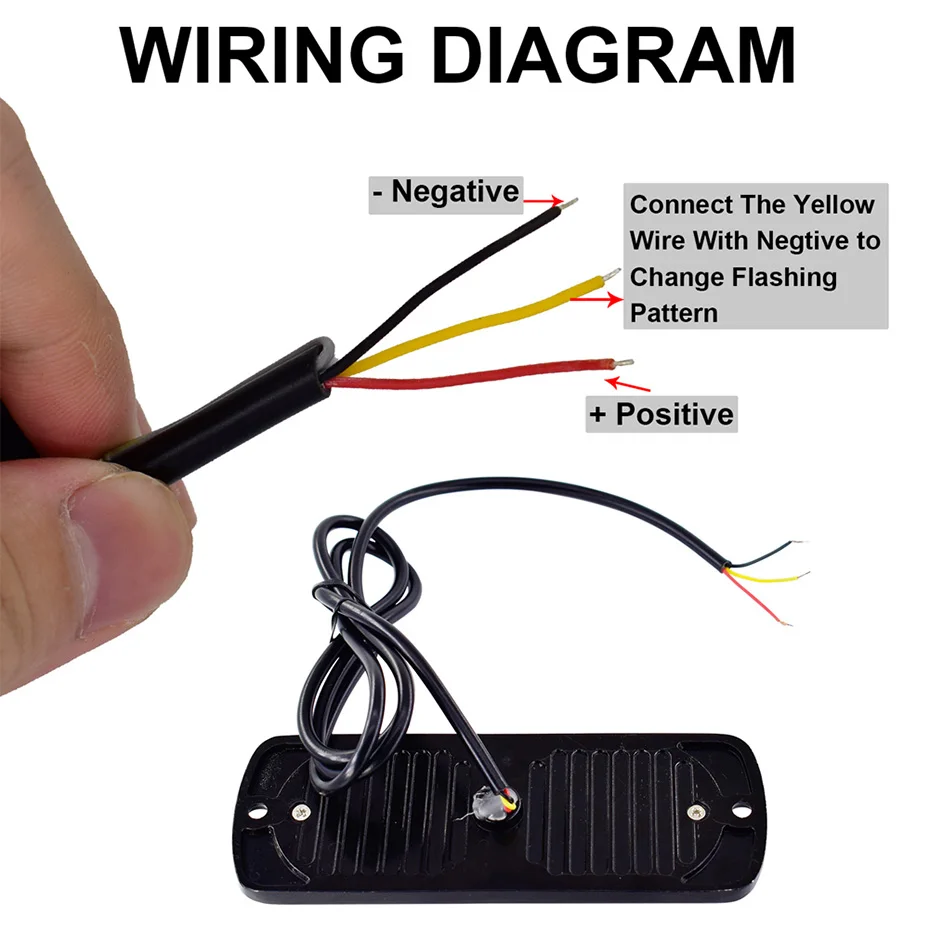
Strobes with 3 wires hook up? | The largest community for ... Good evening all. I'm new. I'm in a tight spot and cant find much info I'm looking for. So I have strobes I just recieved and they 3 wire red (positive) black ( negative) and yellow (synchro). I have a 3 prong rocker switch I'm looking to hook these lights up to and I dont use the cheap about to... PDF Anti-collision Light Systems Installation and Service ... Two wingtip strobe lights that protrude beyond the wingtip, their light converging in front and back of the aircraft within 1200 ft. is an approved anti-collision strobe light system. ENCLOSED WINGTIP Enclosed wingtip anti-collision strobe lights, require a third strobe light on the tail or verti-cal fin, to fill in the required light envelope ...
How To Wire Strobe Lights to a Switch - YouTube In this video, we demonstrate how to wire LED Emergency Strobes to momentary switch. **For permanent installations, be sure to solder your wires or use weath...

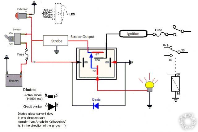
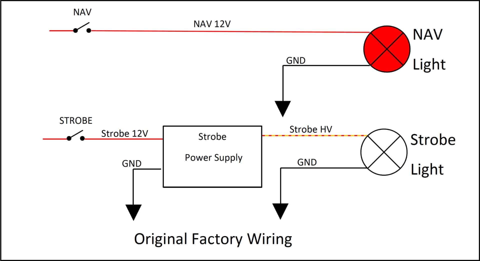
Strobe light wiring diagram
Fire Alarm Horn Strobe Wiring Diagram - Wirings Diagram According to previous, the traces in a Fire Alarm Horn Strobe Wiring Diagram signifies wires. Occasionally, the cables will cross. But, it does not mean connection between the wires. Injunction of 2 wires is generally indicated by black dot at the junction of two lines. There will be main lines that are represented by L1, L2, L3, and so on. PDF 4 Wire Synch Wiring Diagram - 247 Lighting 4 Wire Synch Wiring Diagram 12/24 V-+ S-+ S-+ S-+ S Pattern Power Switch Switch Sync Settings: 1. ... Light 1 Light 2 Light 3 Light 4 Disclaimer: This diagram is to be used as a guide, Use of this guide is at the installers risk. Created Date: 7/31/2019 11:27:03 AM ... 3 Wire Strobe Light Wiring Diagram - Collection - Wiring ... 3 Wire Strobe Light Wiring Diagram from . Print the wiring diagram off plus use highlighters to trace the signal. When you make use of your finger or perhaps the actual circuit with your eyes, it is easy to mistrace the circuit. 1 trick that We 2 to printing a similar wiring plan off twice.
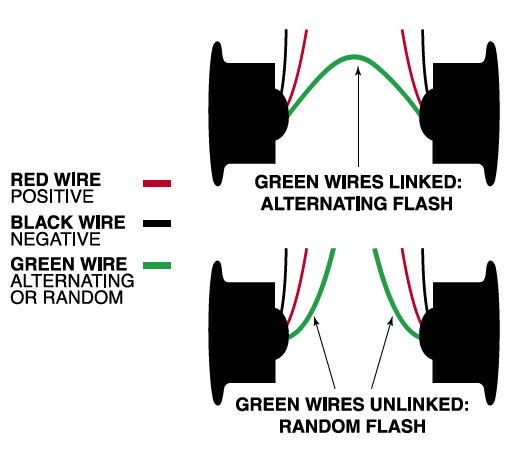
Strobe light wiring diagram. 3 Wire Led Light Wiring Diagram - U Wiring 3 wire led light wiring diagram. The first component is emblem that indicate electrical component from the circuit. 3 Wire Led Light Bar Wiring Diagram wiring diagram is a simplified suitable pictorial representation of an electrical circuitIt shows the. You should have 3 wires at the rear of your LED light or from a pigtail like part A47PB ... 3 Wire Strobe Light Wiring Diagram - easywiring Assortment of strobe light wiring diagram. A wiring diagram is a streamlined standard pictorial depiction of an electric circuit. A wiring diagram is a streamlined standard photographic depiction of an electrical circuit. Which wire is ground on custer 4 led strobe light strl4r. Variety of whelen justice lightbar wiring. Whelen Strobe Light Wiring Diagram Strobe Anti-collision Power Supply. Do not install this product or route any wires in the deployment area of your air bag. Equipment This product contains either strobe light (s), halogen light (s), high-intensity LEDs or a combination of these lights. Do not . WIRING DIAGRAM. This power supply will operate up to 3 strobe light head assemblies. PDF Installation and Maintenance Instructions for Vista ... vista® strobe light assembly, series a safety message to installers of federal signal light systems warning people's lives depend on your safe installa- ... wiring diagram (refer to note 1) from seperate signalmaster cable flashing (flasher "x") strobe pwr supply front strobe action pattern
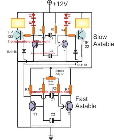
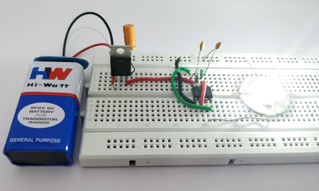
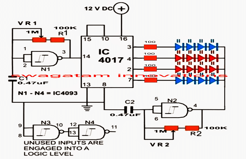
4 Wire Strobe Light Wiring Diagram - Wiring Sample The 4-wire device provides two independent circuits one for the Horn and another for the Strobe. 4 wire tail light wiring diagram wiring diagram is a simplified up to standard pictorial representation of an electrical circuit it shows the components of the circuit as simplified shapes and the power and signal associates amongst the devices. LED Strobe Light Circuit Diagram The complete circuit diagram is shown in the above image. You can either build them on a breadboard or solder them to a Perf Board. The explanation of the circuit is given below. Circuit Explanation: The heart of the strobe light circuit is the 555 Timer which is operating in Monostable mode. The 555 Timer can operate in 3 different modes such ... What are the functions of each wire color for 7679X LED ... Grote's Answer. Grote's 7679x Auxiliary LED Strobe Lights - wiring and flash patterns: Red: To +VDC (fuse@ 3A) Black: To Chassis Ground. White: For steady burn, apply +VDC. Yellow: For Synchronization - Connect yellow wires of all heads together for synchronization (all heads must be set at the same pattern) Strobe Light Wiring Diagram - Collection - Wiring Diagram ... Strobe Light Wiring Diagram. Strobe Light Wiring Diagram from chevy.oldcarmanualproject.com. Print the wiring diagram off plus use highlighters to trace the signal. When you make use of your finger or perhaps the actual circuit with your eyes, it is easy to mistrace the circuit. 1 trick that We 2 to printing a similar wiring plan off twice.
Xprite Chase Light Wiring Diagram - U Wiring Xprite chase light switch wiring diagram. Xprite Rz Series 30 Offroad Rear Chase Led Strobe Light Bar Wiring Diagram Source. 44 Awesome Xprite Chase Light Wiring Diagram Chase Light Bar Lighting Trailer Light Wiring Rj45 Connector Wiring Diagram wiring diagram is a simplified agreeable pictorial representation of an electrical circuit. Xprite chase light wiring diagram. […] PDF NAV/STROBE LIGHT ASSEMBLY - Boeing For ultra-lights, home-builts, experimental aircraft. Wiring (refer to diagram) • Red wire 1 (nav lamp) - Connect to positive input • Red wire 2 (position lamp) - Connect to switch • Black wire connect to ground. (Nav and strobe lamps are internally grounded to the case) • Connector - Operates the strobe lamp. Whelen Strobe Wiring Diagram Whelen Strobe Wiring Diagram The Xenon flash tubes used in Whelen products come in various shapes and sizes. base of the flashtube or attached to the rear of a strobe lighthead. Reversing these wires will discharge the flash tube current through the primary burning. 6 STROBE. OUTLETS. 15 AMP. FUSE. CONTROL. CONNECTOR. POWER. CONNECTOR. WIRING. Whelen Strobe Wiring Diagram - schematron.org Whelen strobe light wiring further whelen led wiring diagram smart moreover wiring diagram for whelen edge 9m further whelen dual avenger wiring diagram along with dodge durango power steering diagrams together with 16 over whelen traffic advisor wiring diagram photograph furthermore truck lite strobe lights lovely 25 unique dual color led ...
PDF Flyleds ACM Strobe Controller Board Installation Follow the wiring diagram as shown to connect the Flyleds Position and Strobe lights to the Aircraft Rear Harness connector. Note that the green plugs are wired in a mirror image of each other at the left and right wings. We recommend using 2 and 3 wire shielded cable for neatness and convenience, however individual wires may also be used.
4 Wire Strobe Light Wiring Diagram - easywiring 4 wire strobe light wiring diagram. This latter point cannot be stressed enough. This diagram shows the basic wiring of two pull stations and two horn strobes to a power supply. A signal on the red wire will override the steady on running light signal on the black wire and cause the unit to strobe according to my contact at custer.
3 Wire Strobe Light Wiring Diagram - Collection - Wiring ... 3 Wire Strobe Light Wiring Diagram from . Print the wiring diagram off plus use highlighters to trace the signal. When you make use of your finger or perhaps the actual circuit with your eyes, it is easy to mistrace the circuit. 1 trick that We 2 to printing a similar wiring plan off twice.
PDF 4 Wire Synch Wiring Diagram - 247 Lighting 4 Wire Synch Wiring Diagram 12/24 V-+ S-+ S-+ S-+ S Pattern Power Switch Switch Sync Settings: 1. ... Light 1 Light 2 Light 3 Light 4 Disclaimer: This diagram is to be used as a guide, Use of this guide is at the installers risk. Created Date: 7/31/2019 11:27:03 AM ...
Fire Alarm Horn Strobe Wiring Diagram - Wirings Diagram According to previous, the traces in a Fire Alarm Horn Strobe Wiring Diagram signifies wires. Occasionally, the cables will cross. But, it does not mean connection between the wires. Injunction of 2 wires is generally indicated by black dot at the junction of two lines. There will be main lines that are represented by L1, L2, L3, and so on.












0 Response to "38 strobe light wiring diagram"
Post a Comment