39 allen bradley safety relay wiring diagram
PDF Adjustable | Installation/Wiring Allen-Bradley, Rockwell Automation, and PowerFlex are registered trademarks of Rockwell Description for option 21 of parameter t221 [Relay Out Sel] corrected. Invalid catalog number for L 1-14 Installation/Wiring. Figure 1.5 Control Wiring Block Diagram. (1) Important: I/O Terminal 01 is... PDF PowerFlex Low Voltage Drives Selection Guide Look to the portfolio of Allen-Bradley safety solutions to help achieve your safety needs. Allen-Bradley PowerFlex 520-Series AC drives combine innovation and ease of use to provide motor control solutions designed to maximize your system performance Rating Wiring. kW Hp Diagram(1).
PDF Safety Products Catalog | Modular Safety Relays Note: For additional Safety Relays connectivity, see the Safety Relays section (page 5-8) of this catalog. See Typical Wiring Diagram on page 3-17 for wiring details. Recommended Logic Interfaces. Description. Safety Outputs.
Allen bradley safety relay wiring diagram
dspace.library.uvic.ca › bitstream › handlePLC Programming For A Water Level Control System: Design and ... Dec 03, 2017 · PLC Programming For A Water Level Control System: Design and System Implementation by Haoqiang Ji B.Sc., Beijing University of Civil Engineering and Architecture, 2013 Allen Bradley Safety Relay Wiring Diagram - Free Catalogs A to Z Category: Guardmaster safety relay manual Show details. Allen Bradley Safety Relay Wiring Diagram - Wiring Diagram. 7 hours ago Allen bradley 1756 of8 wiring diagram sample exelent safety relay wiring image best for wiring diagram. control.com › textbook › relay-control-systemsRelay Circuits and Ladder Diagrams | Relay Control Systems ... Here, we will emulate the exact same high-pressure alarm circuit using an Allen-Bradley MicroLogix 1000 PLC instead of a relay coil: Wiring diagram: Ladder-logic program: Suppose a fluid pressure of 36 PSI is applied to the pressure switch. This is less than the switch’s trip setting of 50 PSI, leaving the switch in its “normal” (closed ...
Allen bradley safety relay wiring diagram. safety relay wiring - Search Reset Push Button - The safety relay is wired into a "Reset" push button on terminal S34. Output Coils K1 and K2 - The safety relay provides a dual channel output Nov 30, 2020 · Allen Bradley Safety Relay Wiring Diagram - allen bradley guardmaster safety relay wiring diagram, allen bradley... Allen Bradley Safety Relay Wiring Diagram China Manufacturers... We are Professional Manufacturer of Allen Bradley Safety Relay Wiring Diagram company, Factory & Exporters "Sticking on the theory of ""Super Quality, Satisfactory service"" ,We have been striving to become a good company partner of you for Allen Bradley Safety Relay Wiring Diagram , allen... GMC-RM002F-EN-P Kinetix Safe Torque-off Feature Safety Reference... For additional information regarding Allen-Bradley safety products, including safety relays, light curtain, and gate interlock applications, refer to the This appendix provides typical wiring diagrams for the Kinetix 6000 and Kinetix 7000 safe torque-off drives with other Allen-Bradley safety products. Allen Bradley Safety Relay Wiring Diagram - Wiring Site Resource For special applications the choice of device type is based on the suitability of. With the new allen bradley sensaguard family of non cont...
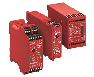
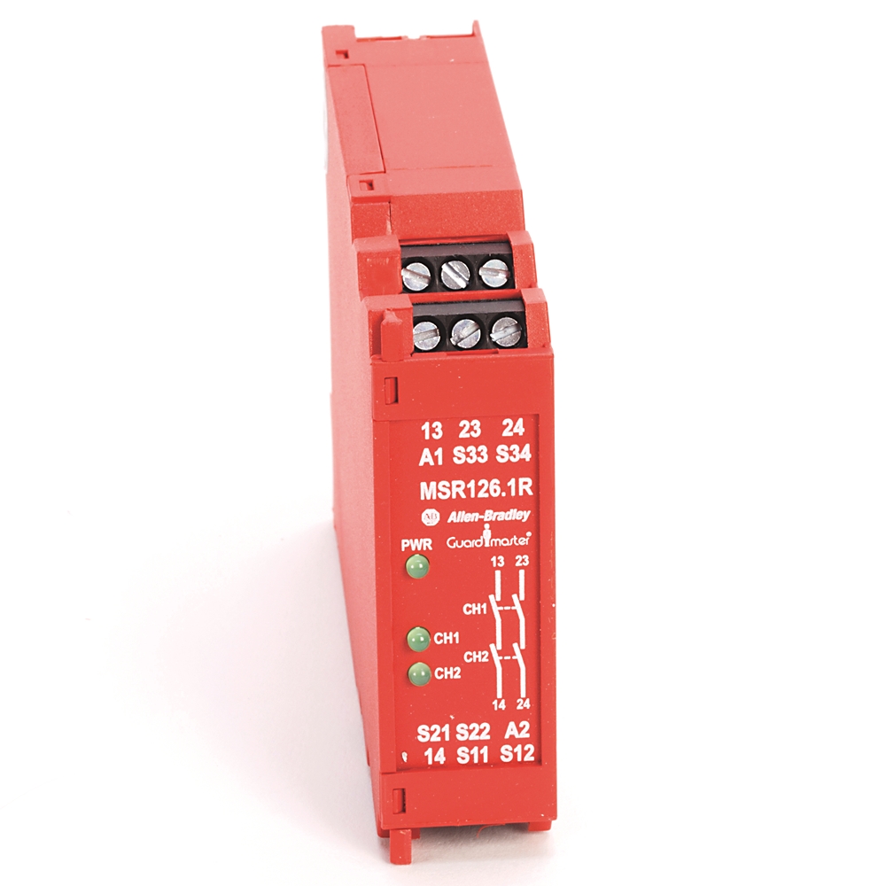
PDF Safety - MSR126R/T The Allen-Bradley Guardmaster Minotaur MSR126R/T is a safety monitoring relay that provides the very basics for safety control systems in a 22.5 mm package. The MSR126R/T is designed for connection to a single channel safety gate, a single channel... Electrical Panel Wiring Diagram | Safety Circuit Panel Schematic The electrical wiring diagram above contains an example of a safety circuit one may find in an industrial environment. The following components are shown here: The MSR304 is an Allen Bradley Safety Relay . It sends a signal through a series of safety switches and E-Stops and reads the signal... literature.rockwellautomation.com › idc › groupsGuardmaster Configurable Safety Relay Wiring Diagram Wiring Diagram. Important User Information ... contact your local Allen-Bradley® distributor or ... The CR30 safety relay performs the logic that monitors the ... How to wire ALLEN BRADLEY soft starter SMC 3 - YouTube Wiring safety relay SRB301 and emergency stop. 3:56. How to wire Soft Starter and contactor. v.1. 4:44.
PDF MicroLogix 1100 Programmable Controllers User Manual Allen-Bradley Programmable Controller Grounding and In-depth information on grounding and wiring Since the master control relay allows the placement of several emergency-stop switches in different The following illustrations show the wiring diagrams for the MicroLogix 1100 controllers. Allen-Bradley Safety Plc 13.08.2008 - Plckenny - TheWikiHow Фото обложки и кадры из видео. Allen-Bradley Safety Plc 13.08.2008, Plckenny. Allen Bradley Guardmaster Safety Relay Wiring Tutorial. Technical Documentation Center | Rockwell Automation 中国 Relays, Safety. Browse documentation on our Literature Library. Find a wide selection of commercial and technical publications that support Allen-Bradley hardware, FactoryTalk software, plus our services and solutions. › safety-relayGuide to Safety Relays and Safety Circuits - PLC Academy Sep 24, 2018 · Allen Bradley Safety Relay It’s here where the use of a safety relay comes in handy! Because you could build a safety circuit just by using normal relays and contactors, but since this quickly can become complicated and involve several components we want to use safety relays.
Guardmaster Safety Relays User Manual
PDF 1766-UM001I-EN-P MicroLogix 1400 Programmable Controllers User... Allen-Bradley Programmable Controller Grounding and Wiring In-depth information on Since the master control relay allows the placement of several emergency-stop switches in different locations Sinking and Sourcing Wiring Diagrams. Any of the MicroLogix 1400 DC embedded input groups can...

Guardmaster Configurable Safety Relay Wiring Diagram
PDF ALLEN-BRADLEY / GUARDMASTER - Documentation: Interrupteurs... Description When it comes to machine safety, Rockwell Automation knows that protection of personnel and equipment is your main concern. Optimize all of these with the new Allen-Bradley SensaGuard family of non-contact switches. Typical Wiring Diagrams.
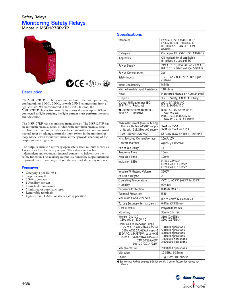
ALLEN-BRADLEY MSR127RP
Programmable logic controller - Wikipedia 1.2 Allen-Bradley. 1.3 Early methods of programming. 2 Architecture. 7 Safety PLCs. 8 PLC compared with other control systems. 8.1 PLC Chip / Embedded Controller. If even one wire were out of place, or one relay failed, the whole system would become faulty.

Improve Efficiency with Wired Safety Controls | Horizon Solutions
allen-bradley safety relay datasheet & applicatoin... - Datasheet Archive allen-bradley safety relay Datasheets Context Search. Catalog Datasheet. Abstract: schematic diagram for heater power controller blown fuse indicator project report wiring diagram motor autotransformer Allen-Bradley bulletin 1502 autotransformer starter Allen-Bradley MV soft starter...

GSR Applications and Wiring Diagrams | PDF | Relay | Switch
Allen Bradley Safety Relay Wiring Diagram - Wirings Diagram Home » Wiring Diagram » Allen Bradley Safety Relay Wiring Diagram. There are two things which are going to be present in any Allen Bradley Safety Relay Wiring Diagram. The first element is symbol that indicate electrical element in the circuit.
Safety Relay. Faakart . Online shop - Industrial Automation ...
Power Relay - Allen Bradley Guardmaster Safety Relay Wholesale... Allen Bradley Safety Relay. Rs 450/ Piece. Voltage Type. DC. Allen Bradley Guardmaster Safety Relay. MSR241P 440R-H23187. View Complete Details.
Door Monitoring Interlock Switch with a Safety Relay and ...
ALLEN-BRADLEY E300 USER MANUAL Pdf Download | ManualsLib Relays ALLEN BRADLEY Guardmaster User Manual. Safety relays (100 pages). Relays Allen-Bradley Guardmaster 440C-CR30-22BBB Wiring Diagram. • Trip Snapshot Simplified Wiring The E300 relay provides an easy means to mount to both IEC and NEMA Allen-Bradley® contactors.
Single-function Safety Relays | Allen-Bradley United States
Allen Bradley | RS Components We have 1352 Allen Bradley products. For a customized and cost-effective solution that provides basic control for standalone machines, turn to the Allen-Bradley® Micro800™ programmable logic controller (PLC) family as your Micro Control System.

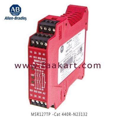
ALLEN-BRADLEY MSR127TP E-STAND: C 440r-n23132 440rn23132 ...
Software Configurable Safety Relay | Allen-Bradley United States This relay is completely integrated with Allen-Bradley Logix controllers and can be configured using Studio 5000 Logix Designer® software or Connected Components Workbench software. Includes two single-wire safety input/output points for interlocking between Guardmaster® safety relays.

Rockwell / Allen-Bradley Minotaur MSR6R/T Single-Function ...
control.com › textbook › relay-control-systemsRelay Circuits and Ladder Diagrams | Relay Control Systems ... Here, we will emulate the exact same high-pressure alarm circuit using an Allen-Bradley MicroLogix 1000 PLC instead of a relay coil: Wiring diagram: Ladder-logic program: Suppose a fluid pressure of 36 PSI is applied to the pressure switch. This is less than the switch’s trip setting of 50 PSI, leaving the switch in its “normal” (closed ...

Allen Bradley 440R-ZBR520AZ1 Safety Relay - Used
Allen Bradley Safety Relay Wiring Diagram - Free Catalogs A to Z Category: Guardmaster safety relay manual Show details. Allen Bradley Safety Relay Wiring Diagram - Wiring Diagram. 7 hours ago Allen bradley 1756 of8 wiring diagram sample exelent safety relay wiring image best for wiring diagram.

Emergency Stop Circuit - PLCS.net - Interactive Q & A
dspace.library.uvic.ca › bitstream › handlePLC Programming For A Water Level Control System: Design and ... Dec 03, 2017 · PLC Programming For A Water Level Control System: Design and System Implementation by Haoqiang Ji B.Sc., Beijing University of Civil Engineering and Architecture, 2013

440R-N23130 Allen Bradley - Industrial Control - Distributors ...

Next Generation Guardmaster Safety Relay (GSR) - PDF Free ...
Safety Relays | Allen-Bradley Finland

60 Lovely Allen Bradley Guardmaster Safety Relay Wiring ...

Interlock Architectures – Pt. 4: Category 3 - Control Reliable
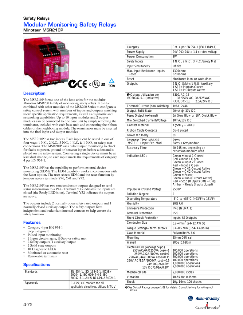
ALLEN-BRADLEY MSR210P
Two Hand Relays
Guardmaster Configurable Safety Relay Wiring Diagram
Safety Relays | Allen-Bradley Finland

Safety Relay PLC Output Resetting : r/PLC
700S-DCP350Z24 NEMA NEMA 600v Safety Relay DC coil | Allen ...

Allen Bradley Guardmaster MSR131RTP 115 V ac Safety Relay Dual Channel with 3 Safety Contacts 2 Auxilary Contacts
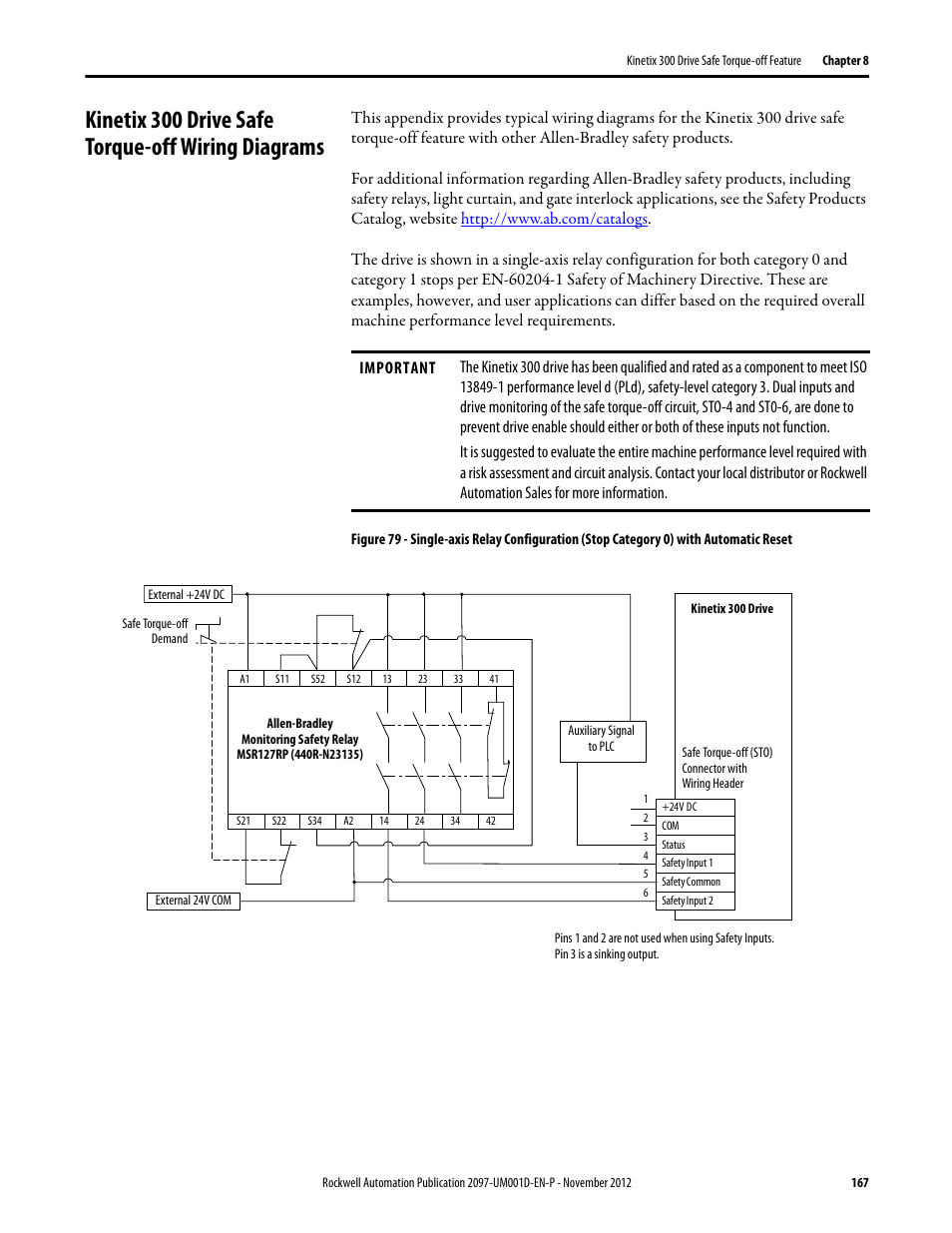
Kinetix 300 drive safe torque-off wiring diagrams | Rockwell ...

Safety Relay png images | PNGWing

Safety PLCs - AutomationPrimer

How To Configure A Guardmaster Safety Relay
Safety - MSR126R/T
Single-function Safety Relays with Delayed Outputs | Allen ...

AB Safety Relays Help. : r/PLC
Next Generation Guardmaster Safety Relay (GSR) Wiring Diagram
How do you scale up safety devices? : r/PLC
Safety Function: SensaGuard Non-contact Interlock Switch with ...
Allen-Bradley Guardmaster 440R-N23213 MSR127 Safety Relay, 24 ...

Safety Relay 440R-N23132 Allen-Bradley Guardmaster MSR127TP
440R-N23122 Guardmaster MSR126R Safety Relay | Allen-Bradley ...
Allen-Bradley Guardmaster Multifunction-delay Expansion ...
Safety - MSR127RP/TP
0 Response to "39 allen bradley safety relay wiring diagram"
Post a Comment