40 4 bit carry look ahead adder circuit diagram
4 Bit Adder Circuit Diagram - Irish Connections 4 Bit Adder Multisim Live. Cs 3410 Spring 2018 Lab 1. Solved 11 Consider The Following Diagram Of A 4 Bit Adder Chegg Com. How To Design A Full Adder Using Shift Registers Quora. Sequential design of a 4 bit adder coa binary subtractor javatpoint circuit discussion ic chip full using logic gates in proteus to vhdl code for 9 four mr bridger s ... Verilog code for Carry Look Ahead adder with ... - Blogger The disadvantage comes from the fact that, as the size of inputs goes beyond 4 bits, the adder becomes much more complex. In this post I have written a Verilog code for a 4 bit carry look ahead adder. For the block diagram and explanation of the logic, you might want to see pages 1 to 3 in this pdf. cla_adder.v module cla_adder
4-Bit Carry Look Ahead Adder | PDF | Electronic Design ... 4-bit Carry Look Ahead Adder - Free download as Powerpoint Presentation (.ppt), PDF File (.pdf), Text File (.txt) or view presentation slides online. We designed an 4-bit carry look ahead adder that operated at 200 MHz and used 16mW of Power and occupied an area of 420x440mm2 Introduction Why is a Carry Look Ahead Adder important? The CLA is used in most ALU designs It is faster compared to ...

4 bit carry look ahead adder circuit diagram
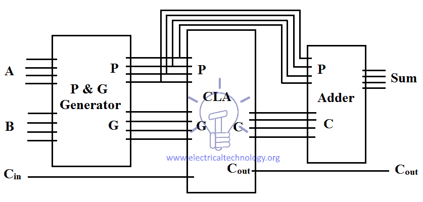
Solved A 4-bit parallel adder is available in integrated ... A 4-bit parallel adder is available in integrated circuit (IC) form. The 74LS283 is 4-bit carry look-ahead (CLA) adder. The pin diagram and logic symbol are shown in Fig. 3. Design the 16-bit parallel adder using four 74LS283 adders, and then show output bits of the 16- input numbers: A = (A47F)16, and B = (759E) 16. 4-bit Carry Look Ahead Adder | Download Scientific Diagram Rajendar Kumar [4] developed the 4-bit, 8-bit and 16-bit Carry Look-ahead Adder (CLA) using Very High speed integrated circuit Hardware Description Language (VHDL). Propagation delay of RCA ... Circuit diagram of carry look-ahead adder | Download ... The circuit of 4-bit Manchester carry look-ahead adder is shown in Fig 3. Fig 3(a) and 3(b) are representing the circuit of propagate and generate signal provider to the adder. The logic blocks are...
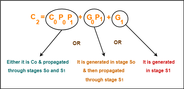
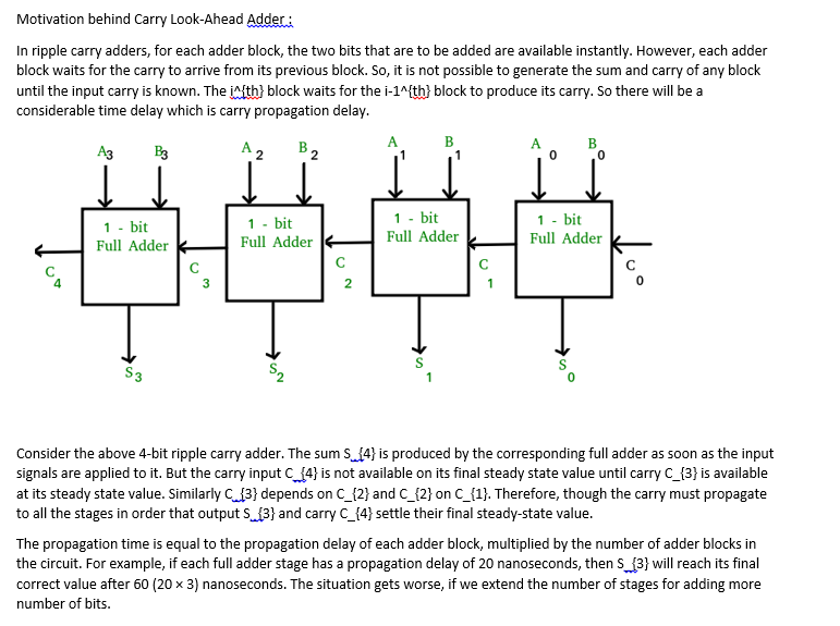
4 bit carry look ahead adder circuit diagram. Ripple carry adder, 4 bit ripple carry adder circuit ... Circuit diagram of a 4-bit ripple carry adder is shown below. Ripple carry adder Sum out S0 and carry out Cout of the Full Adder 1 is valid only after the propagation delay of Full Adder 1. In the same way, Sum out S3 of the Full Adder 4 is valid only after the joint propagation delays of Full Adder 1 to Full Adder 4. 4 Bit Carry Ripple Adder - app.peter2.wldev.wanderlog.com adders with two extra gate delays, while a 32 bit CLA adder is formed when two 16 bit … Carry Look-ahead Adder - Circuit Diagram, Applications May 29, 2016 · The 4-bit Ripple Carry Adder VHDL Code can be Easily Constructed by Port Mapping 4 Full Adder. The following figure represent the 4-bit ripple carry adder. 4-bit Ripple Carry Adder circuit. Digital Adders: Half, Full & BCD Adders, Diagram and Truth ... In this configuration, the ripple carry design is suitably transformed such that the carry logic over fixed groups of bits of the adder is reduced to two-level logic. Below is the circuit diagram for 4-bit look ahead carry adder. T h e s u m a n d c a r r y f o r f o u r b i t a d d i t i o n a r e C 0 = i n p u t c a r r y , C 1 = G 0 + P 0 · C 0 Solved 2. [3+2+2+3 = 10 points] Draw the logic diagram of ... Derive the Boolean equations and draw a 4 bit carry-look-ahead generator circuit. Question: 2. [3+2+2+3 = 10 points] Draw the logic diagram of a full adder circuit. Also show the carry propagator (Pi) and carry generator (Gi). What is the purpose of using carry-look-ahead generator?
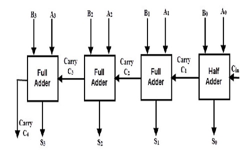
4-bit-carry-lookahead-adder - CircuitVerse Explore Digital circuits online with CircuitVerse. With our easy to use simulator interface, you will be building circuits in no time. PDF 4-bit Carry Ripple Adder - Concordia University So to design a 4-bit adder circuit we start by designing the 1 -bit full adder then connecting the four 1-bit full adders to get the 4-bit adder as shown in the diagram above. For the 1-bit full adder, the design begins by drawing the Truth Table for the three input and the corresponding output SUM and CARRY. The Boolean Expression describing ... › readBCD ADDER:2 digit BCD Adder A 4 bit Adder Subtracter Unit ... Since the 4-bit Code allows 16 possibilities, therefore thefirst 10 4-bit combinations are considered to be valid BCD combinations. The latter six combinations are invalid and do not occur. Here you will see the bcd adder examples, circuit, truth table, verilog and vhdl code for 2 bit, 4 bit, 8 bit & 16 bit bcd adder ciruit, ALU. › serial-binary-adder-inSerial Binary Adder in Digital Logic - GeeksforGeeks Apr 22, 2020 · A single full adder is used to add one pair of bits at a time along with the carry. The carry output from the full adder is applied to a D flip-flop. After that output is used as carry for next significant bits. The sum bit from the output of the full adder can be transferred into a third shift register. Block diagram of Serial Binary Adder:
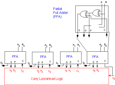
circuitdigest.com › tutorial › full-adder-circuitFull Adder Circuit: Theory, Truth Table & Construction Jun 29, 2018 · Full Adder Circuit: So we know that Half-adder circuit has a major drawback that we do not have the scope to provide ‘Carry in’ bit for addition. In case full adder construction, we can actually make a carry in input in the circuitry and could add it with other two inputs A and B. › half-adderHalf Adder - an overview | ScienceDirect Topics Determine the delay of a 32-bit adder using the full-adder characteristics of Table 2.4 (average delays). 2.3. Design a radix-4 full adder using the CMOS family of gates shown in Table 2.4. Compare delay and size with a 2-bit carry-ripple adder implemented with (radix-2) full-adders (use average delays). Carry Look Ahead Adders - Computer Organization And ... Circuit diagram for a full adder that produces Cg and Cp function is shown below 4 bit Carry Look Ahead Adder Carry generation and carry propagation in terms of the input bits to a 4-bit adder is shown in the figure. We can now write expressions for the output carry C out of each full adder for the 4-bit example. Full Adder 1 Full Adder 2 electricalfundablog.com › adder-classificationsAdder - Classifications, Construction, How it Works and ... Fig. 3 – (a) Block Diagram (b) Circuit Diagram of Half Adder’s Circuit. Full Adder. When 3 bits need to be added, then Full Adder is implemented. It has three one-bit numbers as inputs, often written as A, B, and C in where A and B are the operands and C in is a carry bit from the previous less-significant stage.
Carry Look-Ahead Adder - Working, Circuit and Truth Table
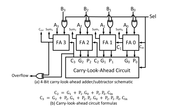
Carry Look-ahead Adder - Circuit Diagram, Applications ... The Carry Look-ahead Adder circuit fro 4-bit is given below. 4-bit-Carry-Look-ahead-Adder-Circuit-Diagram 8-bit and 16-bit Carry Look-ahead Adder circuits can be designed by cascading the 4-bit adder circuit with carry logic. Advantages of Carry Look-ahead Adder In this adder, the propagation delay is reduced.

Ripple look-ahead-header
Carry Lookahead Adder : Truth Table, Circuit, Advantages ... To design either 8-bit, 16-bit or 32-bit parallel adders, then the required number of 4-bit carry lookahead adders can be added using the carry bit. For example, an 8-bit carry lookahead adder circuit diagram can be drawn and implemented using two 4-bit adders with additional gate delays.

Ripple-Carry Adder - an overview | ScienceDirect Topics
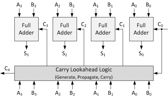
PDF Carry look-ahead adder - Concordia University Fig. 3 Look-Ahead Carry generator The size and fan-in of the gates needed to implement the Carry-Look-ahead adder is usually limited to four, so 4-bit Carry-Look ahead adder is designed as a block. The 4-bit Carry Look Ahead adder block diagram is shown in Fig.4. The delay of such circuit is 4 levels of logic.

King Fahd University of Petroleum and Minerals - ppt download
Carry Look-Ahead Adder - GeeksforGeeks Carry Look-ahead Adder : A carry look-ahead adder reduces the propagation delay by introducing more complex hardware. In this design, the ripple carry design is suitably transformed such that the carry logic over fixed groups of bits of the adder is reduced to two-level logic.

Carry-lookahead adder - Wikipedia
PDF Design, Simulation, and Analysis of ... - IOSR Journals produce an n-bit adder circuit by copying it n-times. That is, here the input carry depends on the output carry generation of the previous cell or block. However, for the Carry Look Ahead Adder (CLA) circuit, the carry-in bits of each cell need not wait for the computation of the output carry of the previous cell.
Solved a) Write Verilog code of 4-bit carry lookahead adder ...
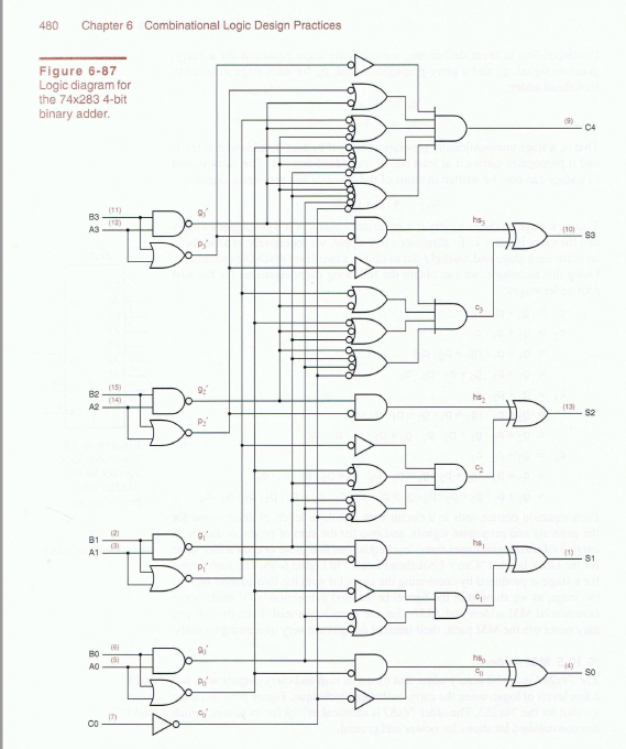
electronicspost.com › full-adderFull Adder - Electronics Post May 09, 2015 · 4-bit full adder circuits with carry look ahead features are available as standard IC packages in the form of the TTL 4-bit binary adder 74LS83 or the 74LS283 and the CMOS 4008 which can add together two 4-bit binary numbers and generate a SUM and a CARRY output as shown below in fig.6.

Carry Look-Ahead Adder - Working, Circuit and Truth Table
4 bit carry look ahead Adder - Seeking inventions Design of a 4 bit carry look ahead adder: If we draw a truth table by taking A, B and Cin as input and Cout as output, we can predict the Co circuit by solving K-MAP of that truth table. TRUTH TABLE A B Cin Cout 0 0 0 0 0 0 1 0 0…
Solved 4) Carry Look-ahead Adder: If: The TPD for | Chegg.com
Can someone draw a circuit diagram of 4 bit carry look ... Answer: * To understand what's the importance of Carry Look Ahead Adder ( CLA ) (also called Parallel Adder) in ALU's , first, you need to realize what led to development of such an adder. Though there are half-adders/ 4-bit ripple adders (also called Serial Adder) available in market, they are ...
Solved 5. Write the code in Verilog and create a Testbench ...
4 Bit Parallel Adder Circuit Diagram - IOT Wiring Diagram 4 Bit Parallel Adder Circuit Diagram. By IOT | January 15, 2022. 0 Comment. Four bit parallel adder scientific diagram electrical4u and subtractor block explain for 4 computer engineering ripple carry gate vidyalay combinational circuits binary javatpoint what is 2 5 electronics coach exploreroots paralle caarry propagate cpa coa solved task 8 ...

Carry Look-Ahead Adder - Working, Circuit and Truth Table
› 3-bit-synchronous-down-counter3 bit Synchronous Down Counter - GeeksforGeeks May 19, 2021 · 3 bit Synchronous Down Counter : In synchronous counter clock is provided to all the flip-flops simultaneously. Circuit becomes complex as the number of states increases. Speed is high. Design : The steps involves in design are . 1. Decide the number of Flip flops – N number of Flip flop(FF) required for N bit counter. For 3 bit counter we ...

Carry-Look-Ahead Adder (8-bit) | Download Scientific Diagram
4-bit parallel adder and 4-bit parallel subtractor ... 4-bit parallel adder and 4-bit parallel subtractor - designing & logic diagram. A parallel adder is an arithmetic combinational logic circuit that is used to add more than one bit of data simultaneously. A full adder adds two 1-bits and a carry to give an output. However, to add more than one bit of data in length, a parallel adder is used.
Homework 6 Solutions 1. Construct a 4-bit ripple-carry adder ...
Carry Look-Ahead Adder - Working, Circuit and Truth Table Circuit Diagram of 4-bit Carry-Lookahead Adder Circuit Diagram of the entire 4-bit CLA Adder We can see that there is no dependency on any intermediate Carry values in any of the equations. On solving the equations, we see that only the input Carry C in is required to calculate all the Sum and Output Carry values.
Delay Efficient All Optical Carry Lookahead Adder | SpringerLink
How to design a four bit adder-subtractor circuit? - EE-Vibes As illustrated in the diagram underneath, a binary circuit may be created by combining an Ex-OR gate alongside every full adder. 4-bit parallel adder and 4-bit parallel subtractor shown below has multiple 4 bit inputs labelled 'A3 A2 A1 A0' & 'B3 B2 B1 B0'. 4 bit binary adder. The carry input of the of the full adder's least ...
Virtual Labs
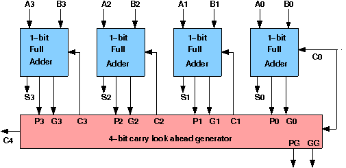
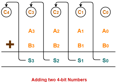
4 bit carry look ahead adder circuit diagram | Gate Vidyalay Also Read-Full Adder Working . 4-Bit Carry Look Ahead Adder- Consider two 4-bit binary numbers A 3 A 2 A 1 A 0 and B 3 B 2 B 1 B 0 are to be added. Mathematically, the two numbers will be added as- From here, we have-C 1 = C 0 (A 0 ⊕ B 0) + A 0 B 0. C 2 = C 1 (A 1 ⊕ B 1) + A 1 B 1. C 3 = C 2 (A 2 ⊕ B 2) + A 2 B 2. C 4 = C 3 (A 3 ⊕ B 3 ...
Delay Depreciation and Power efficient Carry Look Ahead Adder ...
Ripple Carry And Carry Look Ahead Adder - Electrical ... Fig 2 - Ripple carry adder Stages. In 4 bit adder, the time delay for a valid output is the sum of time delay of 4 full adders, if there is an 'n' bit adder, than the time delay will be the sum of time delay of 'n' full adders. It means, higher the bit size of the numbers, the late the answer we will get.So it is not an efficient design for complex and fast working systems.
Carry Look Ahead Adder | 4-bit Carry Look Ahead Adder | Gate ...
PDF Carry Look Ahead Adder - KFUPM Carry Look Ahead Adders Lesson Objectives: The objectives of this lesson are to learn about: 1. Carry Look Ahead Adder circuit. 2. Binary Parallel Adder/Subtractor circuit. 3. BCD adder circuit. 4. Binary mutiplier circuit. Carry Look Ahead Adder: In ripple carry adders, the carry propagation time is the major speed limiting factor as

Carry Look Ahead Adder
Carry Look Ahead Adder | 4-bit Carry Look Ahead Adder ... 4-Bit Carry Look Ahead Adder-. Consider two 4-bit binary numbers A 3 A 2 A 1 A 0 and B 3 B 2 B 1 B 0 are to be added. Mathematically, the two numbers will be added as-. From here, we have-. C 1 = C 0 (A 0 ⊕ B 0) + A 0 B 0. C 2 = C 1 (A 1 ⊕ B 1) + A 1 B 1. C 3 = C 2 (A 2 ⊕ B 2) + A 2 B 2.

Carry Lookahead Adder (Part 1) | CLA Generator
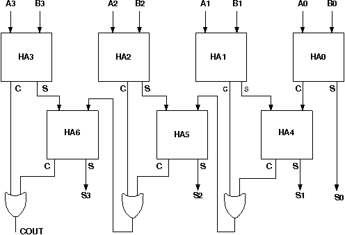
4 Bit Adder Circuit Diagram - Wiring View and Schematics ... Combinational And Sequential Design Of A 4 Bit Adder Ha Circuit Scientific Diagram. 4 Bit Full Adder Using Logic Gates In Proteus The Engineering Projects. Coa Binary Adder Subtractor Javatpoint. 4 Bit Binary Adder Circuit Discussion With Example. Block Diagram Of 4 Bit Ripple Carry Adder Scientific. 9 Four Bit Adder Mr Bridger S Web Page.
Ripple Carry And Carry Look Ahead Adder - Electrical Technology
Circuit diagram of carry look-ahead adder | Download ... The circuit of 4-bit Manchester carry look-ahead adder is shown in Fig 3. Fig 3(a) and 3(b) are representing the circuit of propagate and generate signal provider to the adder. The logic blocks are...
![PDF] Performance Analysis of Different Bit Carry Look Ahead ...](https://asset-pdf.scinapse.io/prod/2560648274/figures/figure-2.jpg)
PDF] Performance Analysis of Different Bit Carry Look Ahead ...
4-bit Carry Look Ahead Adder | Download Scientific Diagram Rajendar Kumar [4] developed the 4-bit, 8-bit and 16-bit Carry Look-ahead Adder (CLA) using Very High speed integrated circuit Hardware Description Language (VHDL). Propagation delay of RCA ...
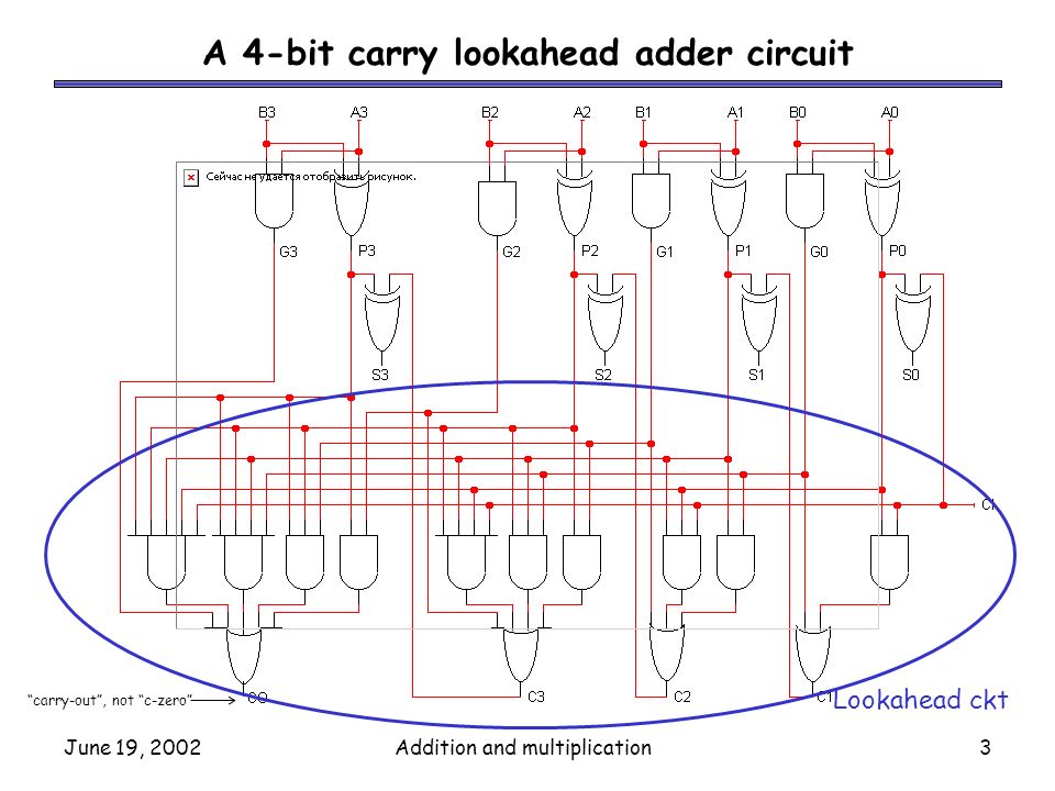
June 19, 2002Addition and multiplication1 Delays in the ...
Solved A 4-bit parallel adder is available in integrated ... A 4-bit parallel adder is available in integrated circuit (IC) form. The 74LS283 is 4-bit carry look-ahead (CLA) adder. The pin diagram and logic symbol are shown in Fig. 3. Design the 16-bit parallel adder using four 74LS283 adders, and then show output bits of the 16- input numbers: A = (A47F)16, and B = (759E) 16.

Carry-Lookahead Adder
Total propagation delay in Carry look ahead adderIn a 4-b ...
Carry Look Ahead Adder | Tinkercad

Carry look ahead adder | Fast carry adder logic circuit ...

Look Ahead Carry Adder | Electrical4U

CSE260 - Carry-Lookahead Adders
Virtual Labs

VLSI UNIVERSE: Carry Look Ahead Adder
Carry Lookahead Adder in VHDL and Verilog with Full-Adders

Carry Look-Ahead Adder - GeeksforGeeks
Carry Look Ahead Adder
![Solved] Statement (I): The carry look-ahead adder is a fast ...](https://storage.googleapis.com/tb-img/production/20/05/F1_U.B_Madhu_16.05.20_D3.png)
Solved] Statement (I): The carry look-ahead adder is a fast ...

Explain 4 bit CLA adder implementation.
Carry Look Ahead Adder | 4-bit Carry Look Ahead Adder | Gate ...
Carry Look-ahead Adder - Circuit Diagram, Applications ...

Carry-lookahead adder - Wikipedia
Solved) : Please Complete 4 Bit Carry Look Ahead Adder ...
Carry Look Ahead Adder

High performance 8 bit cascaded carry look ahead adder with ...
0 Response to "40 4 bit carry look ahead adder circuit diagram"
Post a Comment