40 block diagram to state space
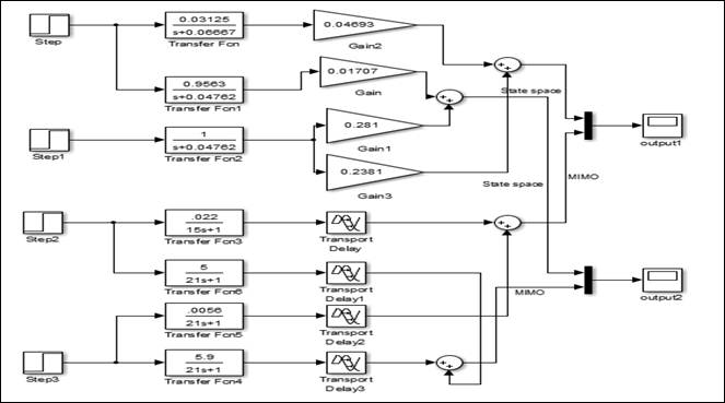
How to represent block diagram with two inputs to state space? From your diagram we can see that your system is linear, The output y (t) can be written as. y (t)=y1 (t)+y2 (t) y1 (t) is the response of your system to the input u1 when u2=0. y2 (t) is the response of your system to the input u2 when u1=0. I suppose you know how to find the ss representation for each subsystem. PDF 3.2.3 Block Diagram of Di fferential Equation Models We will draw a block diagram for this differential equation. A systematic procedure is to start writing the differential equation as a state-space model and then draw a block diagram for this state-space model. We found a state-space model on page 53, namely (3.13), (3.14). Dynamic Systems 59 The model is repeated here: x˙1= x2(3.37) x˙2= 1 m (−K
Solved Derive the state-space representation of the ... Derive the state-space representation of the function given below and draw the block diagram according to the state-space representation. Set the initial states to zero. Derive the state-space representation of the function given below and draw the block diagram according to the state-space representation. Set the initial states to zero.

Block diagram to state space
Introduction: State-Space Methods for Controller Design The equations in the block diagram above are given for the estimate . It is conventional to write the combined equations for the system plus observer using the original state equations plus the estimation error: . We use the estimated state for feedback, , since not all state variables are necessarily measured. After a little bit of algebra ... PDF 2.14AnalysisandDesignofFeedbackControlSystems State ... In state-determined systems, the state variables may always be taken as the outputs of integrator blocks. A system of order n has n integrators in its block diagram. PDF State-Space Models and the Discrete-Time Realization Algorithm ECE4710/5710, State-Space Models and the Discrete-Time Realization Algorithm 5-5 5.2: Working with state-space systems State-space to transfer function In the prior example, we saw it is possible to convert from a difference equation (or transfer function) to a state-space form quite easily.
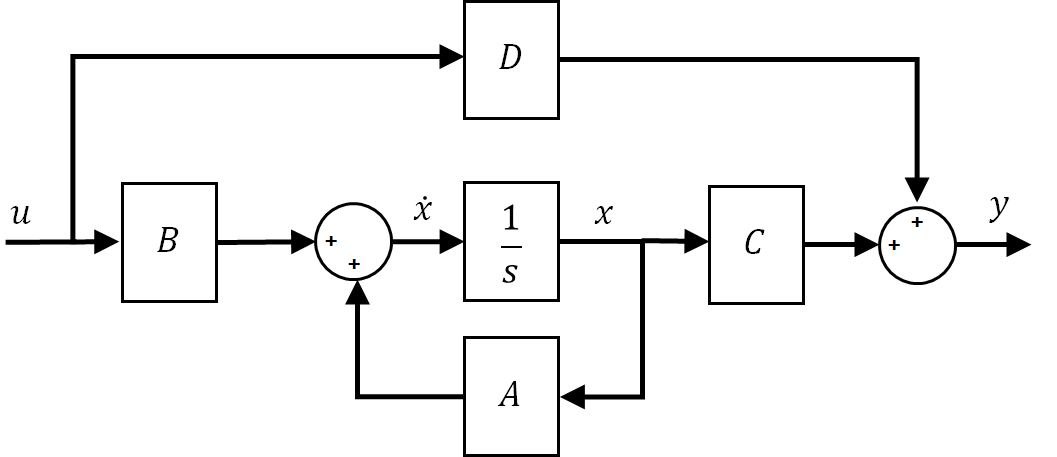
Block diagram to state space. state space transfer function representation state space representation transfer function representation Assume that we are only interested in the input-output relation: transfer function Then, a system can be represented by a block with an input and output. One can represent a large system as an interconnection of block diagrams of subsystems. PDF Using the State-Space and Transfer Function Blocks in Simulink State-Space block from the Continuous sub-menu of the Simulink library. Complete the model with the Step and Scope blocks as shown in Fig. 1. Fig. 1. Basic system model using the State-Space block. At this point the model is very general, and an equation of any order can be set up for solution in the block parameters. The equation inside the ... Implement linear state-space system - Simulink - MathWorks ... The State-Space block implements a system whose behavior you define as x ˙ = A x + B u y = C x + D u x | t = t 0 = x 0, where x is the state vector, u is the input vector, y is the output vector, and x 0 is the initial condition of the state vector. The A, B, C, and D matrices can be specified as either sparse matrices or dense matrices. Transfer function to block diagram in state space analysis ... How to draw block diagram from given transfer function in state space analysis,Transfer function to block diagram conversion,Full Series-Semiconductor Device...
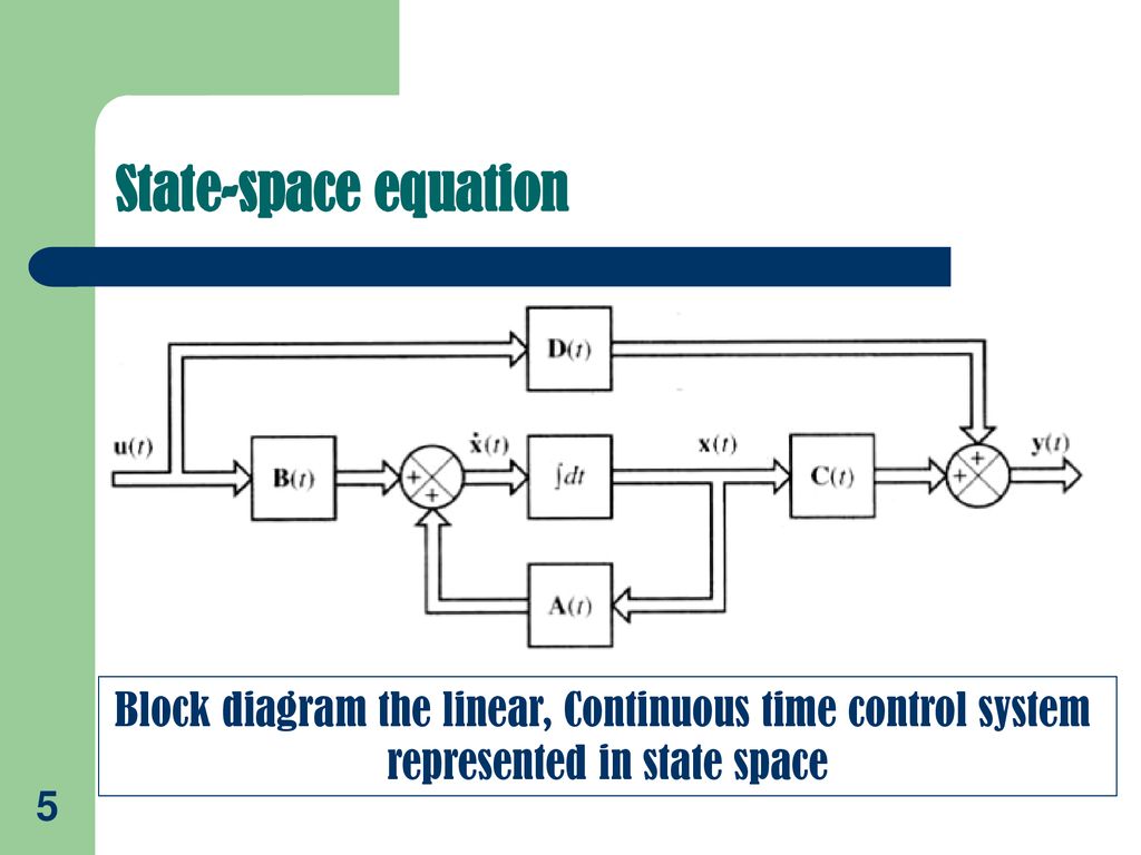
PDF powered by INTRODUCTION TO CONTROL SYSTEMS IN SCILAB State space representation Block diagram representation of the state space equations . Control Systems in Scilab page 8/17 Step 8: State space representation of the RLC circuit In order to write the space state representation of the RLC circuit we perform the following steps: ... PDF Transfer Functions and State Space Blocks The block diagram for this process is shown in Figure 4.1. uB1 sC D A ++ + ˙x+ input y output Figure 4.1: State space representation of the systemx0= Ax+ Bu,y= Cx+ Du, The whole process is captured in theState Space Block. This block is found in the Continuous group. State-Space (Simulink Reference) - Northwestern University The State-Space block implements a system whose behavior is defined by where xis the state vector, uis the input vector, and yis the output vector. The matrix coefficients must have these characteristics, as illustrated in the following diagram: Amust be an n-by-n matrix, where n is the number of states. Block diagram representation of the state space equations ... Download scientific diagram | Block diagram representation of the state space equations. from publication: State-Space model of a mechanical system in MATLAB/Simulink | This paper describes ...
› regulated-power-supplyRegulated Power Supply-Block Diagram,Circuit Diagram,Working Aug 13, 2018 · Regulated Power Supply – Block Diagram. A regulated power supply essentially consists of an ordinary power supply and a voltage regulating device, as illustrated in the figure. The output from an ordinary power supply is fed to the voltage regulating device that provides the final output. PDF LECTURE 1 - Princeton University plex diagrams. The general procedure to obtain the final state-space system remains. same: Stack the states of all subsystems in a tall vector. x and compute ˙ using the state and output equations of the individual blocks. SYSTEM DECOMPOSITION. Block diagrams are also useful to represent complex systems as the interconnection simple blocks. sysml.org › tutorials › sysml-example-tutorialSysML Example Tutorial: Griffin Space Vehicle Project This SysML Example Tutorial features a hypothetical Griffin Space Vehicle Project example to illustrate best practices for specifying System-of-System (SoS) complexity using the Systems Modeling Language (SysML). PDF 3.1 State Space Models - Rutgers University The block diagram for this decomposition is given in Figure 3.1. U(s) V(s) V(s)/U(s) Y(s)/V(s) Y(s) Figure 3.1: Block diagram representation for (3.17) Equation (3.17a) has the same structure as (3.6), after the Laplace transformation is applied, which directly produces the state space system equation identical to (3.9). It remains to find ...
Block diagram representation of the state space equations ...
Solved Problem 2 From Block diagram to State-Space (25pts ... Transcribed image text: Problem 2 From Block diagram to State-Space (25pts) Given the following block diagram, with 2.0 Gfi = 2, G2 = 2, G = 3, Gp 1.0s + 5.0 H = 5, H2 = 1.0s + 3.0 a. (50%) Convert this system into state-space form, accounting for the multiple inputs and out- puts. There are several ways to transfer the block diagram into state-space, but let's try to remodel the state-space ...

Block Diagram of a State-Space Model of a SISO Dynamical ...
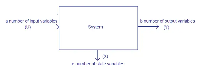
Control Systems - State Space Model - Tutorialspoint The state space model of Linear Time-Invariant (LTI) system can be represented as, X ˙ = A X + B U. Y = C X + D U. The first and the second equations are known as state equation and output equation respectively. Where, X and X ˙ are the state vector and the differential state vector respectively. U and Y are input vector and output vector ...

Block diagram of an observer-based state space controller ...
block diagram to state space - YouTube About Press Copyright Contact us Creators Advertise Developers Terms Privacy Policy & Safety How YouTube works Test new features Press Copyright Contact us Creators ...
QUBE-Servo State Space Block Diagram - Quanser
How to get state-space equations form from a block diagram? This is the block diagram that I'd like to transform into a state-space representation, where u1 and u2 are inputs and y1 and y2 are the outputs of the system. I tried to place state variables on the diagram and go from there (is there a cleaner way to do this?): I am not sure how to go about from here. The $\frac{1}{s+1}$ block is

State Space Representation as Block Diagram | Block diagram ...
How to get the state-space model of a dynamic system - x ... Image: State-space model Xcos block diagram - mechanical system position response csim() As you can see, we have the same response as for the Xcos block diagram model, the only difference being that the unitary step time is 0 s for the Scilab model and 0.1 s for the Xcos model.
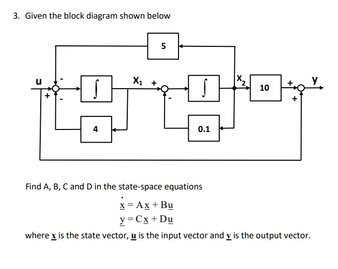
SOLVED:Given the block diagram shown below 10 0.1 Find A, B ...
Implement discrete state-space system - Simulink ... The Discrete State-Space block implements the system described by. where u is the input, x is the state, and y is the output. The matrix coefficients must have these characteristics, as illustrated in the following diagram: A must be an n -by- n matrix, where n is the number of states. B must be an n -by- m matrix, where m is the number of inputs.

The block diagram of a system with one input u and two ...
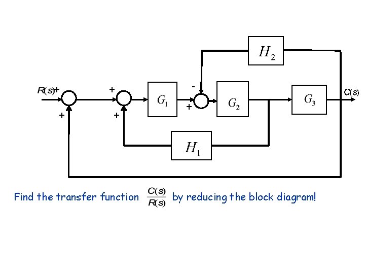
Control Systems - Block Diagram Algebra - Tutorialspoint This block diagram is shown in the following figure. Output of this block diagram is - Y ( S) = G ( s) R ( s) + G ( s) X ( s) (Equation 4) Compare Equation 3 and Equation 4, The first term ' G ( s) R ( s) ′ is same in both equations. But, there is difference in the second term.
Solved Simplify the block diagram and show it as a feedback ...
Control System I EE 411 State Space Analysis Draw a direct form realization of a block diagram, and write the state equations in phase variable form, for a system with the differential equation Solution we define state variables as x 1 =y, x 2 =y&,and x 3 =y&&+13 u, ١٦ then the state space representation is 1 3 2 1 3 2 1 3 2 3 1 2 7 19 13 117 7( 13 ) 19 13 26 13 7 19 13 26 13 y x x x x ...
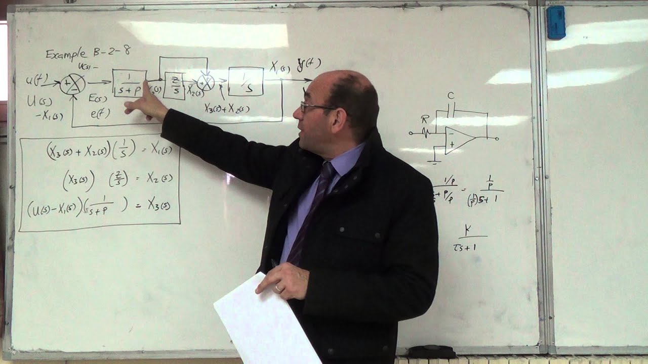
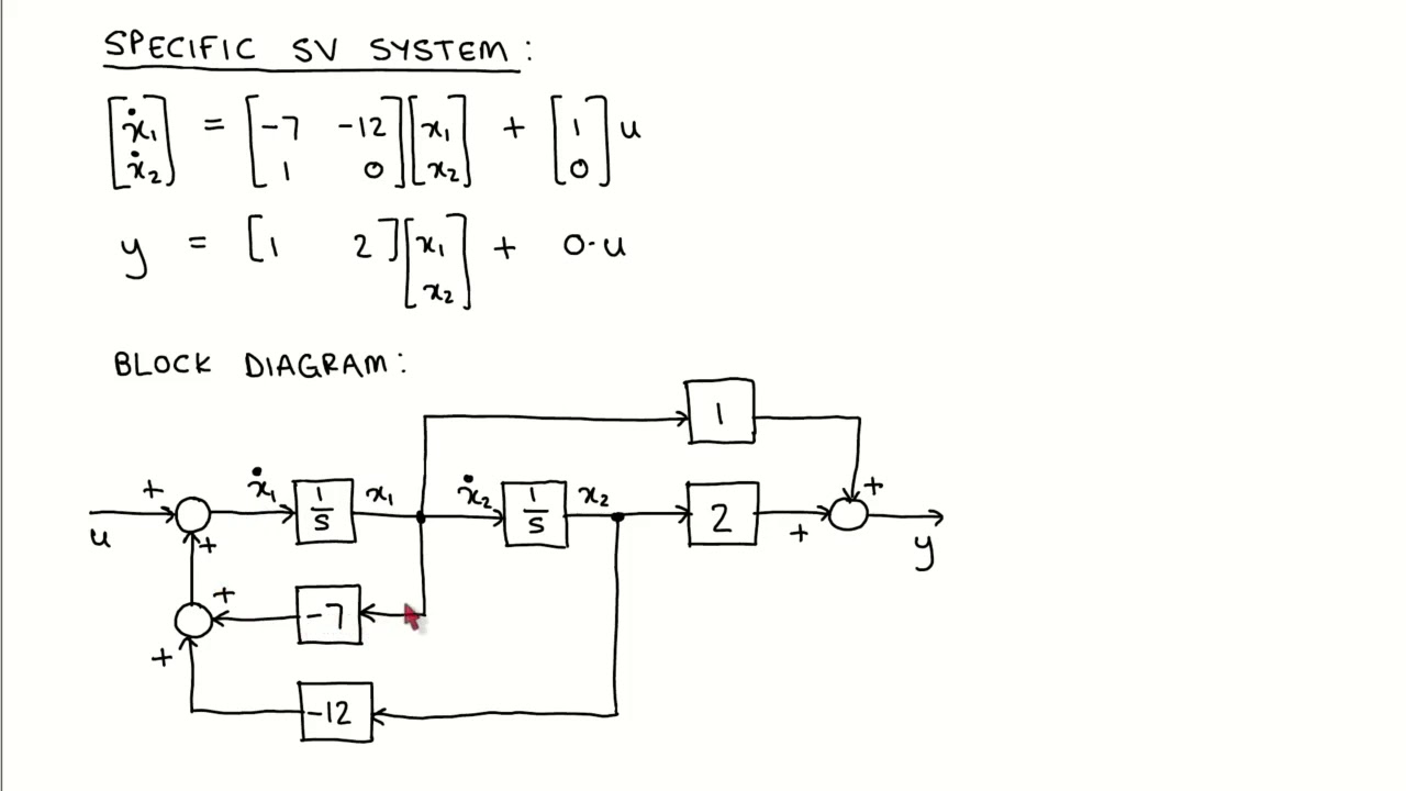
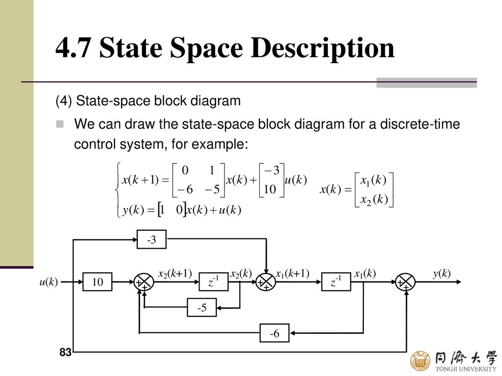
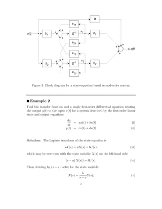
Example on Deriving the State Space Model from the Block Diagram, 22/2/2016
Implement linear state-space system - Simulink The State-Space block implements a system whose behavior you define as x ˙ = A x + B u y = C x + D u x | t = t 0 = x 0, where x is the state vector, u is the input vector, y is the output vector, and x 0 is the initial condition of the state vector. The A, B, C, and D matrices can be specified as either sparse matrices or dense matrices.

Block diagram of the state-space representation. | Download ...
PDF Section 2 Block Diagrams & Signal Flow Graphs Signal Flow Graphs vs. Block Diagrams Signal flow graphs and block diagrams are alternative, though equivalent, tools for graphical representation of interconnected systems A generalization (not a rule) Signal flow graphs -more often used when dealing with state‐space system models Block diagrams -more often used when dealing with

Converting a Transfer Function to State Space representation ...
Block Diagram Simplifier - schematron.org Simplify models of systems with interconnected components using block- diagram reduction; Manipulate linear models as transfer-function or state-space data. Consider the block diagram shown in the following figure. Let us simplify (reduce) this block diagram using the block diagram reduction rules. Reduction.
State Space Representation
Differential Equation - State Space | ShareTechnote How to represent Differential Equation to a special form of Matrix equation called State Space? DE - Equation to Block Diagram Home : When you are given with relatively simple differential equations, you would normally solve those equation in computer using a regular DE solving function (like ode functions in Matlab or ...
State Variable Modeling
bloc2ss - Block-diagram to state-space conversion The strings 'transfer' and 'links' are keywords which indicate the type of element in the block diagram.. Case 1 : the second parameter of the list is a character string which may refer (for a possible further evaluation) to the Scilab name of a linear system given in state-space representation (syslin list) or in transfer form (matrix of rationals).
State variable control 3: Block diagrams
Linear Control System EE 711 MIMO State Space Analysis and ... Draw a direct form realization of a block diagram, and write the state equations in phase variable form, for a system with the differential equation Solution we define state variables as x 1 =y, x 2 =y&,and x 3 =y&&+13 u, ١٦ then the state space representation is 1 3 2 1 3 2 1 3 2 3 1 2 7 19 13 117 7( 13 ) 19 13 26 13 7 19 13 26 13 y x x x x ...

File:Typical State Space model with feedback.svg - Wikimedia ...
PDF State-Space Models and the Discrete-Time Realization Algorithm ECE4710/5710, State-Space Models and the Discrete-Time Realization Algorithm 5-5 5.2: Working with state-space systems State-space to transfer function In the prior example, we saw it is possible to convert from a difference equation (or transfer function) to a state-space form quite easily.

State Space Homework - Control Systems in Mechanical ...
PDF 2.14AnalysisandDesignofFeedbackControlSystems State ... In state-determined systems, the state variables may always be taken as the outputs of integrator blocks. A system of order n has n integrators in its block diagram.
Converting Signal Flow Graphs to State-Space Form by Hand ...
Introduction: State-Space Methods for Controller Design The equations in the block diagram above are given for the estimate . It is conventional to write the combined equations for the system plus observer using the original state equations plus the estimation error: . We use the estimated state for feedback, , since not all state variables are necessarily measured. After a little bit of algebra ...

2.4 Block diagram representation to state space
8.3: State-Space Realization of Transfer Function Models ...

State Space Equations to Block Diagram (Different answer to ...
Solved a. Derive the state-space form directly from the ...
Basics of State Space Modeling
State space analysis, state of a system, state variables.
Dynamic model in state space - JPE

File:Typical State Space model with feedback.svg - Wikimedia ...
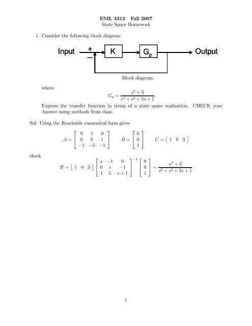
State Space HW solution

State-Space Methods - an overview | ScienceDirect Topics

Control Tutorials for MATLAB and Simulink - Aircraft Pitch ...

Xcos vs. Simulink® – Continuous time library conversion – x ...
Modeling in the Time Domain - ppt download
Study on Dynamics of Saponification Process Using State Space ...
Block Diagrams state space representation transfer function ...
Discription of Computer- - ppt download

Bijles regeltechniek, dynamica, control - HFC Coaching
State-Space Representation of Continuous Systems | SpringerLink

Modern Control - Lec07 - State Space Modeling of LTI Systems

State Space Representations of Linear Physical Systems
State space courses
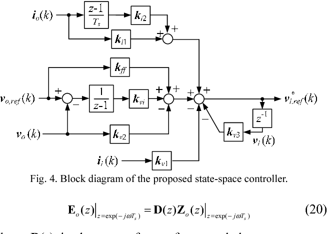
Figure 4 from Discrete state-space voltage controller for ...

1-Block-diagram representation of a state-space model ...
0 Response to "40 block diagram to state space"
Post a Comment