37 motor control center wiring diagram
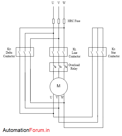
Amazing Motor Control Wiring Diagram 4 Wire 220 To 3 Plug Motor control wiring diagram. Wiring diagrams show the connections to the controller. Star delta y δ 3 phase motor starting method by automatic star delta starter with timer. Motor control animation start stop 3 wire control. Three phase motor connection schematic power and control wiring installation diagrams. Three Phase Motor Power & Control Wiring Diagrams Three Phase Motor Connection STAR/DELTA Without Timer - Power & Control Diagrams. Three Phase Motor Connection Star/Delta (Y-Δ) Reverse / Forward with - Timer Power & Control Diagram. Starting & Stopping of 3-Phase Motor from more than One Place Power & Control diagrams. Control 3-Phase Motor from more than Two buttons - Power & Control ...
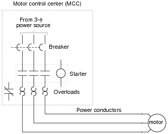
Fine Beautiful Motor Control Center Wiring Diagram ... Ge electric motor wiring diagram motor control center wiring diagram. It shows the components of the circuit as simplified shapes and the facility and signal associates with the devices. Wiring diagrams and equipment from zero to hero an mcc comprises three buses for a three phase system and the cabinet consists of a circuit breaker a motor ...
Motor control center wiring diagram
new.abb.com › low-voltage › productsStarting solutions - Motor protection and control (A-Z Low ... Get the perfect match. Motor starting is the most common application in the world's industry. When it comes to open starter, you can easily select your direct-on-line, reversing and star-delta starter, in kit form, through our selection tables. Motor Control Center Wiring Diagram | Electrical diagram ... Motor Control Center Wiring Diagram. Edgefx Kits. 12k followers . Types Of Electrical Wiring ... Two Speeds One Direction Three Phase Motor Connection Power and Control Diagrams Abbreviations:O/L = Over Load RelayNO = Normally OpenNC = Normally CloseLow = Low SpeedHigh = High Seed 2 Speeds 1 Dire. Mastering Motor Control Center (MCC): Wiring diagrams and ... Mastering Motor Control Center (MCC): Wiring diagrams and equipment from zero to hero An MCC comprises three buses for a three-phase system and the cabinet consists of a circuit breaker, a motor starter, and a control transformer; however, the actual contents vary widely as per requirements.
Motor control center wiring diagram. en.wikipedia.org › wiki › Motor_controllerMotor controller - Wikipedia A motor controller is a device or group of devices that can coordinate in a predetermined manner the performance of an electric motor. A motor controller might include a manual or automatic means for starting and stopping the motor, selecting forward or reverse rotation, selecting and regulating the speed, regulating or limiting the torque, and protecting against overloads and electrical faults. Ac Motor Wiring Diagram - The Wiring Jan 4, Wiring Diagram Schematic, Doerr Hosier Conference Center Resource Engineering, Motor Parts Marathon Electric Motor Parts, Doerr Motor.Doerr lr capacitor wiring diagram as well as century ac motor wiring diagram to moreover 3 sd fan motor wiring diagram v moreover 5 hp baldor capacitor wiring diagram together with wire diagrams easy. › alternator-wiring-diagramAlternator Wiring Diagram: A Complete Tutorial | EdrawMax Below given are some alternator wiring diagrams that are used for different purposes. Let’s have a look at their connections. 3 Wire Alternator Wiring Diagram Source: . This is a three-wire alternating wiring diagram showing the connections between the different components of a circuit. (PDF) eaton-motor-control-basic-wiring.pdf | Dominic Jay ... Standard Diagram Symbols TD03309004E For more information visit: Technical Data Basic Wiring for Page 4 Effective: April 2007 Motor Contol Circuitry of a Starter The two circuits of a motor starter are the power and con- Separate voltages supplied by Control Power Transformers. trol circuits.
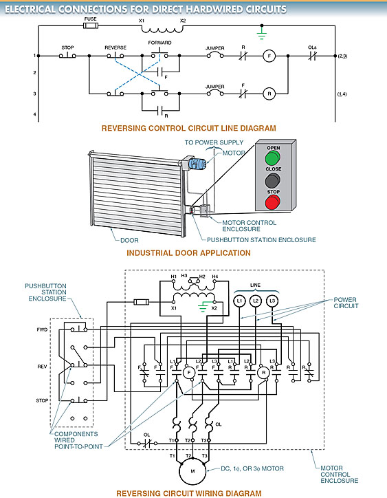
PDF GI-2.0: Typical Wiring Diagrams - Rockwell Automation Note: In this publication the line diagrams show the control circuits only - power circuits are omitted for clarity, since they can be traced readily on the wiring diagrams (heavy lines). A wiring diagram gives the necessary information for actually wiring-up a group of control devices or for Motor Panel Wiring Diagram - Wiring Diagram Line Motor Panel Wiring Diagram Wiring Diagram Line Wiring Diagram ... system scientific microcontroller 1000x648px installation b diagrams grizzly g9249 user 68 92 original mode mastering center mcc from zero hero manualzz i m an engineer 90 pdf link free https bit ly 30wxg5z facebook easy8 sliding gate 57 circuits 20 fast no broken at freshdevices ... Low-voltage motor control centers | Low-voltage - power ... Siemens tiastar industrial motor control centers (MCC) combine time-proven designs and components with the latest in technological advances to meet most applications. No matter how customized your needs may be, you can be assured that you are getting a finished product that represents the state-of-the-art in low-voltage motor control technology. 2 Speeds 1 Direction 3 Phase Motor Power and Control Diagrams 2 Speeds 1 Direction 3 Phase Motor Power and Control Diagrams. Electrical Technology. 22 Less than a minute. Two Speeds One Direction Three Phase Motor Connection Power and Control Diagrams. Abbreviations: O/L = Over Load Relay. NO = Normally Open. NC = Normally Close. Low = Low Speed.
Motor Control Circuits | Motor Control Wiring Diagrams ... Summary : Motor contactor (or "starter") coils are typically designated by the letter "M" in ladder logic diagrams. Continuous motor operation with a momentary "start" switch is possible if a normally-open "seal-in" contact from the contactor is connected in parallel with the start switch, so that once the contactor is energized it maintains power to itself and keeps itself ... Motor Control Wiring Diagram Symbols - Collection - Wiring ... Motor Control Wiring Diagram Symbols. Motor Control Wiring Diagram Symbols from docs.autodesk.com. Print the wiring diagram off plus use highlighters to trace the signal. When you make use of your finger or perhaps the actual circuit with your eyes, it is easy to mistrace the circuit. 1 trick that We 2 to printing a similar wiring plan off twice. PDF Basic Wiring for Motor Contol - Eaton Basic Wiring for Motor Contol Circuitry of a Starter Two-Wire Control Two-Wire Control circuits — or Low Voltage Release One of the common control wiring circuits used is known as Two-Wire or Low Voltage Release (LVR). It utilizes a main-tained contact type of pilot device — such as a thermostat, float switch or presence sensor. Figure 6 Motor Starter Wiring Diagram Pdf Download - Wiring Diagram ... Wiring Diagram Pics Detail: Name: motor starter wiring diagram pdf - Starter Motor Wiring Circuit Diagram Pdf Terminals Control Relay 3; File Type: JPG; Source: szliachta.org; Size: 248.83 KB; Dimension: 1080 x 608; What's Wiring Diagram
CENTERLINE 2100 Motor Control Centers Selection Guide
› worksheets › ac-motorAC Motor Control Circuits Worksheet - AC Electric Circuits A very common form of latch circuit is the simple “start-stop” relay circuit used for motor controls, whereby a pair of momentary-contact pushbutton switches control the operation of an electric motor. In this particular case, I show a low-voltage control circuit and a 3-phase, higher voltage motor:
EATON LV MCC C
First Class Full House Wiring Diagram Motor Control Center ... Wiring diagrams for receptacle wall outlets. Full house wiring diagram. Complete house wiring diagram full house wiring in hindi wiring diagram नमस क र द स त. Be sure to get your copy of my big new ebook. See how to wire it right. View at the. Complete guide to home electrical wiring. House wiring diagrams and project guides.

AIM Manual - Page 57 | Single-Phase Motors and Controls ...
Motor Starter Wiring Diagrams - VintageMachinery.org ... Improper wiring can Kill, Injure, Start Fires, Burn Out Motors or any/all of the above. 3ph Starter/3ph Motor¶ Line Voltage Control three phase (3ph) motor starter controlling a three phase motor (rev 08 Aug 2006) The above wiring diagram assumes your magnetic starter has a 240V coil.

Motor Circuit Control Panel, Motor Protection Control Panel ...
Low-voltage motor control centers documentation - Siemens USA Siemens motor control center wiring diagrams are at your fingertips within seconds. Use the tool below to quickly find and download one-line diagrams. E-House solutions - the fast-track project approach E-Houses are customized, pre-assembled, and pre-tested modular power substations. They are ideally suited for use in situations where fast ...
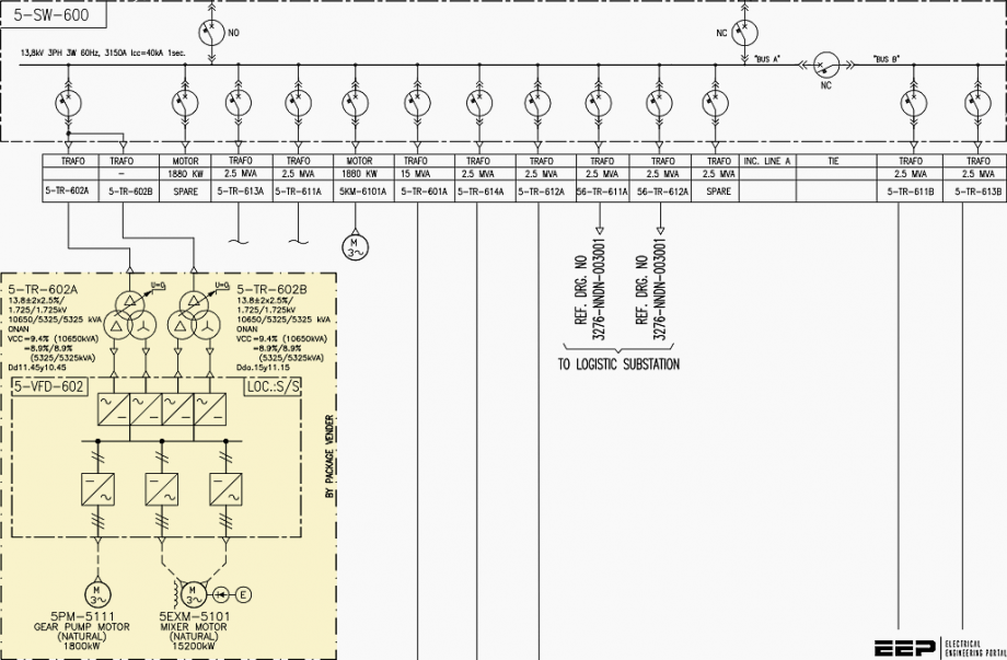
Mastering Motor Control Center (MCC): Wiring diagrams and ...
› holdenHOLDEN - Car PDF Manual, Wiring Diagram & Fault Codes DTC Kindly please help me with a complete wiring diagram for Alfa Romeo 155v6 2.5 167(AIC)..1995 to show the Bosch Motronic 88 pin outs and the location on the car of the ignition COTROL module.Thanks a mil and Happy New Year from Nairobi.
Industrial Motor Control Starters | Magnetic Motor Starter ...
Basic wiring for motor control - Technical data guide | EEP Wiring diagrams show the connections to the controller. Wiring diagrams, sometimes called " main " or " construction " diagrams, show the actual connection points for the wires to the components and terminals of the controller. Basic wiring for motor control - Technical data. They show the relative location of the components.

The Basics of Motor Control Centers (MCCs) | EEP
Motor Control Center Wiring Diagram | Electrical ... Motor Control Center Wiring Diagram | Electrical & Electronics with regard to Motor Wiring Diagram by admin Through the thousand photographs on the net about motor wiring diagram, we selects the very best libraries along with ideal quality only for you, and now this photos is one of photos selections in your greatest photographs gallery about Motor Wiring Diagram.

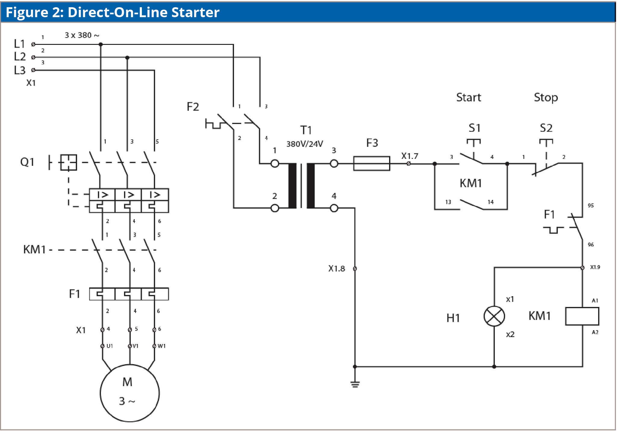
Wiring Diagram and Control of Direct On Line 3-Phase Motor ...
230v Motor Wiring Diagram - U Wiring Fasco Motor Wiring Diagram. When you make use of your finger or perhaps stick to the circuit with your eyes its easy to mistrace the circuit. Three Phase Motor Connection STARDELTA Without Timer Power Control Diagrams. A wiring diagram usually gives information about the. Baldor Single Phase 230v Motor Wiring Diagram Sample.

Motor Control Center Explanation | MCC Panel wiring diagram | MCC Panel Wiring
PDF Motor control centers— low voltage - Eaton motor control center to be tested to a North American guideline specifically written for low-voltage motor control centers, unlike C37.20.7 that is a guideline for testing metal-enclosed switchgear up to 38 kV. Eaton's Freedom Arc-Resistant motor control center is tested in accordance with CSA C22.2 No. .22-11
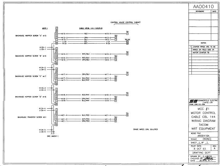
mcc #1 motor control cable wiring diagram
PDF AC motor control circuits - ibiblio wiring diagram calls for something different. It is your job to improvise a solution! file 00836 Question 4 Interpret this AC motor control circuit diagram, explaining the meaning of each symbol: L1 L2 Run M1 To 3-phase motor power source M1 Also, explain the operation of this motor control circuit. What happens when someone actuates the ...

Motor Soft Starter png images | PNGWing
5-wire Stepper Motor Wiring Diagram - U Wiring 5-wire stepper motor wiring diagram. Stepper motors with six wires are unipolar and have one winding per phase like the bipolar steppers but with a center tap. 3-wire radiator fan motor. There are slight differences on how the different variant of stepper motors work ie. But today I can say that this type of engine.

Motor Control Center Wiring Diagram | Electrical diagram ...
PDF Wiring Diagram Book - Daltco Wiring Diagram Book A1 15 B1 B2 16 18 B3 A2 B1 B3 15 Supply voltage 16 18 L M H 2 Levels B2 L1 F U 1 460 V F U 2 L2 L3 GND H1 H3 H2 H4 F U 3 X1A F U 4 F U 5 X2A R Power On Optional X1 X2115 V ... MOTOR 3CT TO 120 V SEPARATE CONTROL * OT is a switch that opens when an overtemperature condition exists (Type MFO and MGO only) T1 T3 MOTOR 3 2 L2 T2 ...
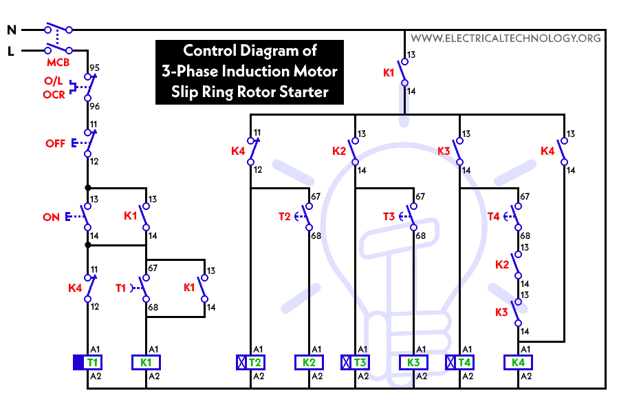
Three Phase Slip Ring Rotor Starter Control & Power
Square D Mcc Bucket Wiring Diagram - schematron.org Section 1—About the Model 6 Motor Control Center 10 Section 4—Installing the MCC. that they agree with the wiring diagrams provided. the Mag-Gard or PowerPact selection tables in the Square D. Digest.Note: The Square D Model 6 Motor Control Center and buckets are no longer a current production item.
Electric Motor Control Wiring Methods | Electrical A2Z
Motor Control Center Design Guide 600V - PAKTECHPOINT This article is for the design, basic concept and testing of 600 V class motor control centers to be installed indoors in non-hazardous areas.Main keywords for this article are Motor Control Center Design Guide, Motor Control Center Layout, MCC Schematic Diagram, Motor Control Center Wiring Diagram, MCC Panel Components.

Motor Control Center Design Guide 600V | PAKTECHPOINT
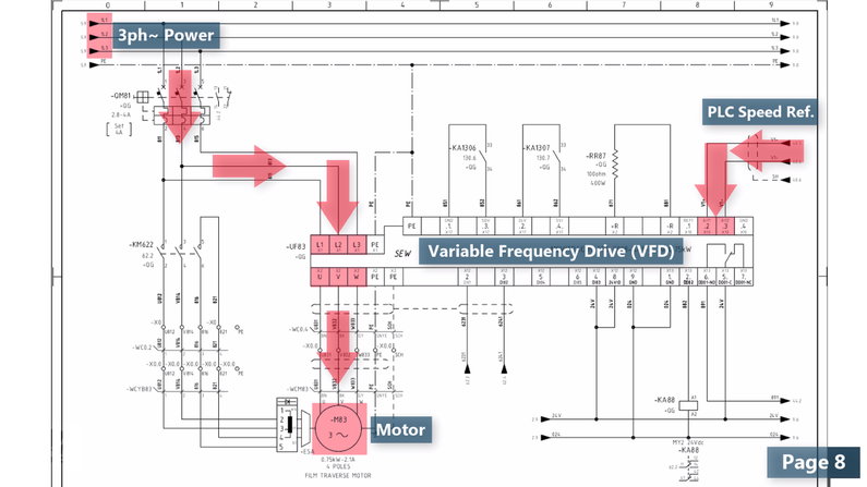
Vfd Control Wiring Diagram - The Wiring Enjoy the speed control you have with your Mitsubishi VFD . A wiring diagram is a simplified standard photographic depiction of an electrical circuit. Electrical Contactor Wiring Diagram additionally Star Pin-out connection diagram for VFD-M Fig. Vfd control wiring diagram. The VFDs showed in the video are the D720S (230V single phase) and the D720 […]
AC Motor Control Circuits Worksheet - AC Electric Circuits
› threads › 2011-2012-complete2011-2012 Complete Wiring Diagram - Jeep Wrangler Forum Jan 08, 2012 · I came across this info on another site when I was looking for my 2012 stereo wiring diagram. Much more info than I needed but may be helpful to others. FYI the speaker wires were 100% accurate for my 2012 JK. Hopefully someone else finds this info useful too. If you read carefully almost all...
Motor Control Center Explanation | MCC Panel wiring diagram ...
6 Wire Stepper Motor Wiring Diagram - Electrical Wiring ... The basic wiring diagram is shown below in figure 2. It stands for the physical parts of the electrical circuit as geometrical shapes, with the real power and also link connections between them as slim sides. Determine how many lead wires your motor has 4, 6, or 8 wires. Determine how many lead wires your motor has 4, 6, or 8 wires.

Square D Motor Control Center Wiring Diagram | Well pump ...
Mastering Motor Control Center (MCC): Wiring diagrams and ... Mastering Motor Control Center (MCC): Wiring diagrams and equipment from zero to hero An MCC comprises three buses for a three-phase system and the cabinet consists of a circuit breaker, a motor starter, and a control transformer; however, the actual contents vary widely as per requirements.
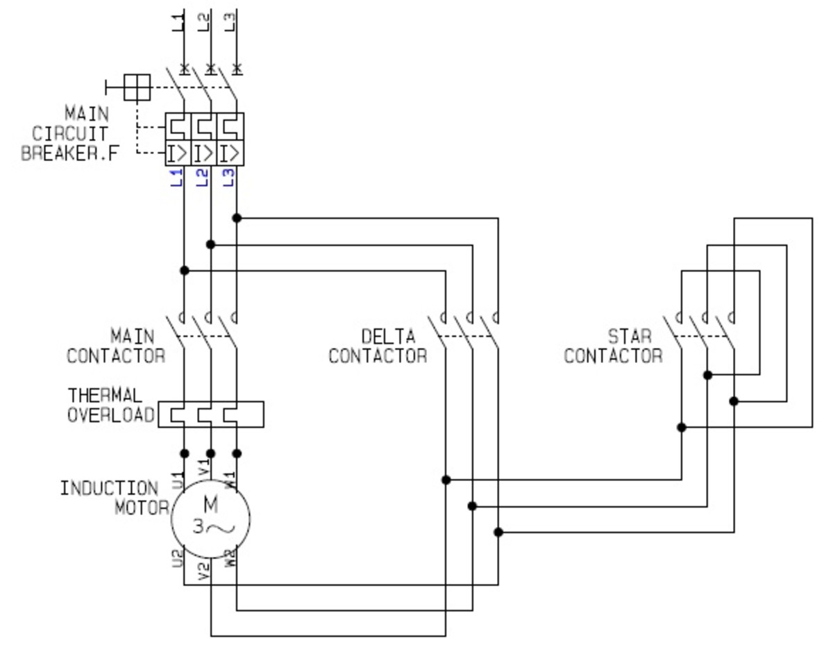
Using Star-Delta Motor Control (With Circuit Diagrams ...
Motor Control Center Wiring Diagram | Electrical diagram ... Motor Control Center Wiring Diagram. Edgefx Kits. 12k followers . Types Of Electrical Wiring ... Two Speeds One Direction Three Phase Motor Connection Power and Control Diagrams Abbreviations:O/L = Over Load RelayNO = Normally OpenNC = Normally CloseLow = Low SpeedHigh = High Seed 2 Speeds 1 Dire.

Buy Model 4 - Square D Motor Control Center
new.abb.com › low-voltage › productsStarting solutions - Motor protection and control (A-Z Low ... Get the perfect match. Motor starting is the most common application in the world's industry. When it comes to open starter, you can easily select your direct-on-line, reversing and star-delta starter, in kit form, through our selection tables.

Wiring Diagram and Control of Direct On Line 3-Phase Motor ...

AIM Manual - Page 54 | Single-Phase Motors and Controls ...
ReliaGear™ LV MCC Motor control center

Ultimate wiring guide - Power mosfet AND live center cycle ...
How to Read a PLC Wiring Diagram (Control Panel Wiring ...
Motor control circuits - Types - Electrical - Industrial ...

Different Types of Industrial Control Panel Components - ETechnoG

DOL Starter Connection and Wiring Diagram with OLR - ETechnoG
Schneider Electric Model 6 Motor Control Centers

File:Wiring diagram of motor control centre on pump station ...
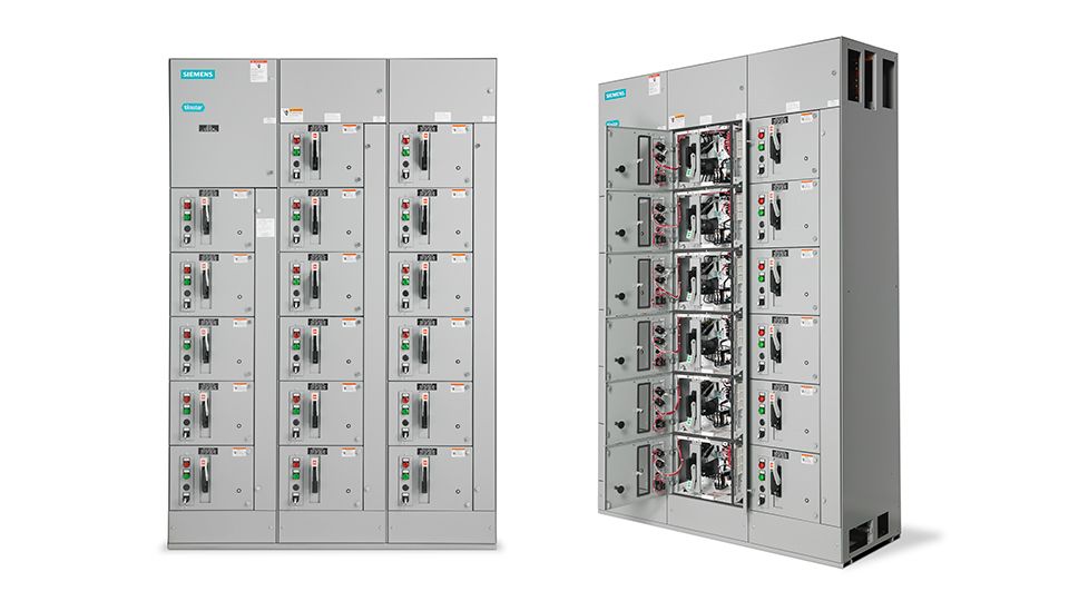
Standard motor control centers | Low-voltage motor control ...
Mastering Motor Control Center (MCC): Wiring diagrams and ...

Motor Control Circuit Forward Reverse | Wiring and Connection ...

Drafting for Electronics--MOTORS AND CONTROL CIRCUITS (part 2)

Types of Motor Control Schematics | Electrical circuit ...
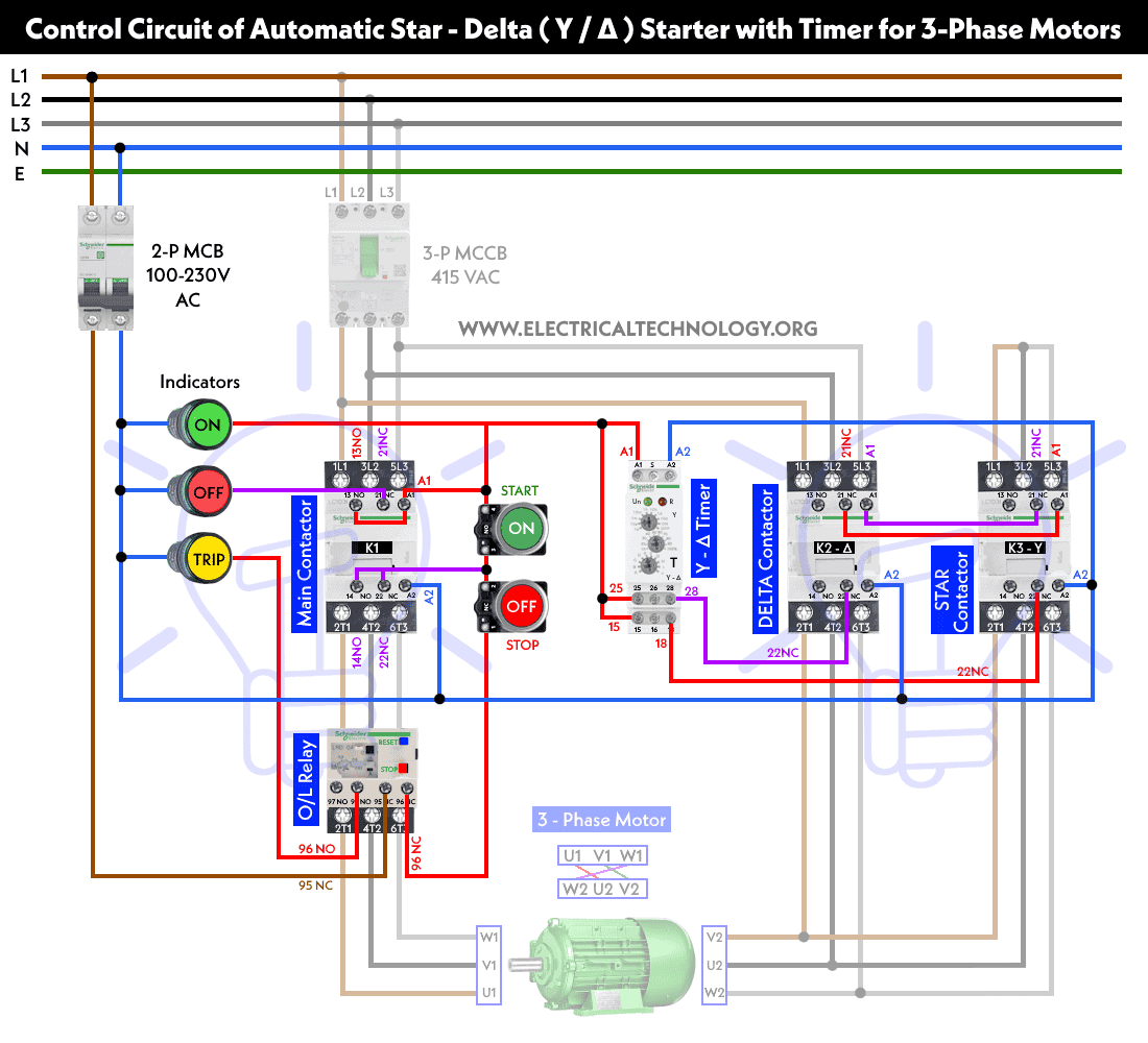
Star Delta Starter - (Y-Δ) Starter Power, Control & Wiring ...

Reconditioned Allen Bradley 2100 Series Three Section MCC ...
0 Response to "37 motor control center wiring diagram"
Post a Comment