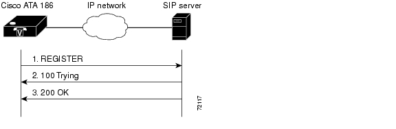
37 sip call flow diagram
SIP and H.323 - Oracle This section's call flow diagrams show how SIP and H.323 messages flow between SIP and H.323 devices, with the Oracle® Enterprise Session Border Controller positioned between the two entities so it can perform translations. The following two sample scenarios with Fast Start appear in the diagrams below, although other scenarios are possible: Call Flow Diagram :: SIP3 Documentation Call Flow Diagram Overview Here is an example of the SIP3 Call Flow Diagramwhich allows to analyze a call as a sequence diagram. It's the key feature of a Call Details Widget. The diagram visualizes cryptic information about the call and represents it as a combination of call events between participants. Events
SIP to SS7 ISUP Interworking - Dialogic Integrated Media ... SS7 ISUP To SIP Interworking Call Flow Diagram Field Descriptions The field options vary depending on which selection is made. Tables below display the cardinality when selecting each option within the individual fields. The mappings below are based on RFC 3398 and Q.1912.5 (03/2004). ACM Mapping Procedure/ACM Mapping Condition
Sip call flow diagram
Call flow diagrams - ibm.com The call flow diagram displays the sequence of messages that are sent between agents and servers. The SIP Modeling Toolkit provides some base classes that specify all the messages and responses specified in RFC 3261. The base classes can be user agents Session Initiation Protocols (SIPs), and so on. Microsoft Teams call flows - Microsoft Teams | Microsoft Docs Call flows in various topologies. Illustrates the use of call flows in various topologies. For each topology, the section enumerates all supported flows and illustrates how these flows are used in several use cases. For each use case, it describes the sequence and selection of flows using a flow diagram. Teams with Express Route optimization. SBC SIP-to-SIP Basic Call Processing Flow SBC SIP-to-SIP Basic Call Processing Flow The following diagram illustrates the SBC Edge basic SIP-to-SIP call processing. Figure : SBC Basic Call Processing Flow The call is received by the SBC. The Source IP addresses is matched against the Federated IP addresses contained in all the Signaling Groups (SG).
Sip call flow diagram. Call Flow Diagram - Screen Detailed Analysis for VoIP To look for the flow of a call you should select the call from the CDR screen and click on the flow button to see. The Terms of The Flow of A Call In the flow screen, you will meet with two main columns, the left side shows the connection between us and the customer; the right side shows the connection between us and our vendor. Unified Communications Call flow in an Enterprise Network ... Detailed call flow is shown here, 3. Call flow: IP Phone to H.323 Voice Gateway with Gatekeeper In this scenario, Phone A is registered to the CUCM. Phone B is connected to a carrier's CO switch. Below diagram illustrates this call setup between two IP phones registered to the same CUCM. Creating call flow diagrams - ibm.com To create a call flow diagram: Procedure In the Project Explorer view, right-click the UML package; then click Add Diagram > Call Flow Diagram. In the Call Flow Name field, type a name for the diagram, and click OK. This name is also used to name the UML collaboration and the interaction instance. Basic SIP Call Flows & Troubleshooting Commands - Cisco The call flow is as follows: 1. User A calls User B. 2. User B answers the call. 3. User B disconnects the call. 2. Call flow between Gateway-to-Cisco SIP IP Phone Call—Successful Call Setup and Call Hold Below diagram illustrates a successful gateway-to-Cisco SIP IP phone call setup and call hold.
PDF NG9-1-1 Call Flow - Assure911 Figure 1- Call Flow Diagram The Standard NG9-1-1 Network has the same Functional Elements (FEs) in each Data Centers for redundancy. The acronyms are explained in the text that follows. The blue boxes represent additional FEs with the i3 NENA Standard architecture and design. SIP Call Flow Examples - WhichVoIP This will then display the SIP call flow diagram for that call. SIP Call Flow for Outbound Call In Figure 2 below you will find the SIP message flow for an outbound call from a phone through the PBX and out to the PSTN (Public Switch Telephone Network). The SIP messages used in the outbound call flow are as follows: How to Analyze SIP Calls in Wireshark - Yeastar Support Click the Flow Sequence button we can see the graph of this call with some details: SIP signaling flow between different UA. Direction, source and dest port of RTP stream. Codec of the RTP stream. 2) Filter one SIP call. In SIP protocol, we can use call-id, from-tag, to-tag to identify a call. SIP Registration and Invite Call flow ... "A" will initiate a SIP session by sending "INVITE" request (M1) to the proxy server. The proxy server will challenge "A" by sending "407" response (M2). "A" will acknowledge it by sending "ACK" (M3) message. Then "A" will send "INVITE" request with authentication details. Proxy 1 will verify the changes and forwards INVITE to Proxy 2. (M5).
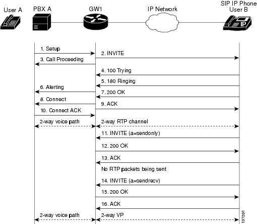
SIP call flow diagram [10] | Download Scientific Diagram Download scientific diagram | SIP call flow diagram [10] from publication: Performance of Various Codecs Related to Jitter Buffer Variation in VoIP Using SIP | Briefly speaking, there are two ... SIP call flow diagram. | Download Scientific Diagram Download scientific diagram | SIP call flow diagram. from publication: Quality of Service Analysis of VoIP Services | VoIP and Service | ResearchGate, the professional network for scientists. Sip Ivr Call Flow Diagramsip Ivr Call Flow Diagram ... Sip Ivr Call Flow Diagramsip Ivr Call Flow Diagram Free Download 2022 by antone.ruecker. Find The BestTemplates at vincegray2014. PDF SIP Call Flows - Cisco Appendix B SIP Call Flows Call Flow Scenarios for Successful Calls Call Setup and Hold Figure B-2 illustrates a successful phone-call setup and call hold. In this scenario, the two end users are User A and User B. User A is located at PBX A. PBX A is connected to Gateway 1 (SIP gateway) via a T1/E1. ...
SIP Call Flows
UCCE Inbound Call Flow - LinkedIn Based on that, here are the different ladder diagrams: Session Initiation Protocol (SIP) - PSTN Gateway sends the call to the CVP and the CVP sends to ICM SIP - CUCM sends the call to ICM and...

CUCM SIP Call Flow Troubleshooting - UCPros
sipcallflow - softswitchngn - Google Search SIP Call Flow. In a SIP call there are several SIP transactions. An SIP transaction consists of several requests and answers and the way to group them in the same transaction is by means of CSeq parameter. Basic SIP session setup involves a SIP UA client sending a request to the SIP URL of the called endpoint (UAS), inviting it to a session.
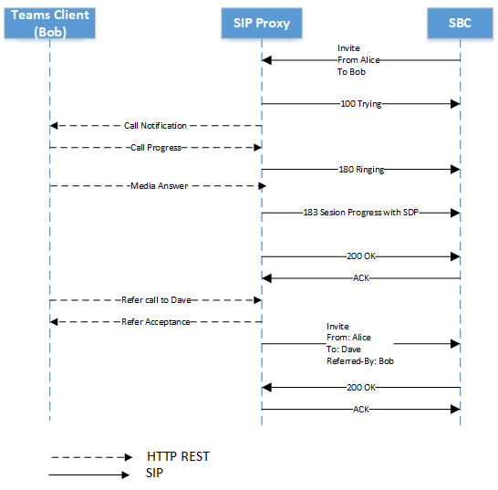
Phone System Direct Routing - Microsoft Teams | Microsoft Docs
Callflow Sequence Diagram Generator download - SourceForge Download Callflow Sequence Diagram Generator for free. Callflow Sequence Diagram Generator. The callflow sequence diagram generator is a collection of awk and shell scripts that will take a packet capture file that can be read by wireshark and produce a time sequence diagram. This is useful to view & debug SIP callflows or other network traffic
Call Hold SIP Service example: Sequence chart
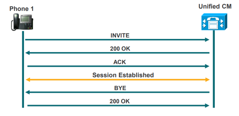
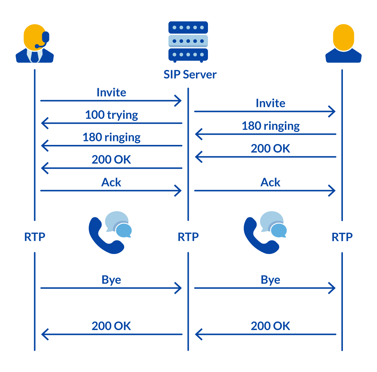
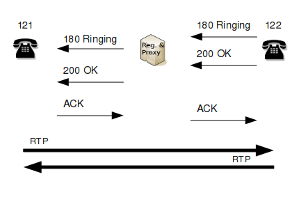
SIP - Basic Call Flow The following image shows the basic call flow of a SIP session. Given below is a step-by-step explanation of the above call flow − An INVITE request that is sent to a proxy server is responsible for initiating a session. The proxy server sendsa 100 Trying response immediately to the caller (Alice) to stop the re-transmissions of the INVITE request.
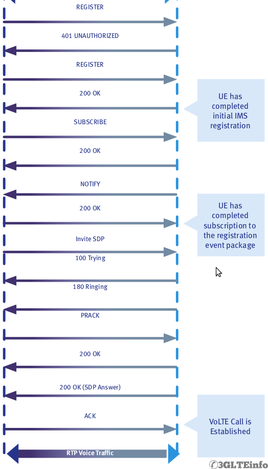
VoLTE Call Flow and Procedures - Voice Over IP Tutorial
PDF Analyze SIP Call Signaling Flow - Cisco Figure 8: Call Flow 6 Create a Call Ladder Diagram Step 1 Selectadatasource.Choosefromthefollowingoptions: •LiveLogCollection-TheGroupTypefieldisdisplayed.Clickonthedrop-downarrow,andselectadevicegroup ... Analyze SIP Call Signaling Flow Understand a Call Ladder Diagram.
SIP signalling- the registration process and setting up a SIP ...
What is a VoIP Call Flow Diagram | Call Flow Solutions A call flow diagram is widely used in sales and customer service calls. Reading scripts can make you sound robotic and unfeeling. In fact, according to a survey conducted in 2018, 78% of customers claim they have a better customer experience if the representative doesn't sound like they are reading from a script.
Sip Troubleshooting - 503 service unavailable - Octa Networks
GSM, 3G, SIP, H.323 Telecom Call Flows SIP originating call flow. The call flow includes the authentication procedure between the SIP client and server. All messsages in this flow can be clicked to access complete message structure. H.323 Call Flow The call flow diagram presents the flow of an H.323 call.
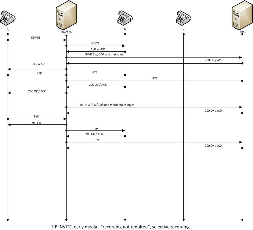
Early Media Call (recording not required)
Basic Call Flow - Genesys One session—One SIP recording session containing all the media streams of both participants in the call. The following diagram describes the call flow: This page was last edited on April 2, 2020, at 11:53.
Call Flow Diagram :: SIP3 Documentation
Creating SIP call flow sequence diagrams from network traces Whenever I am writing some sort of documentation of SIP call flows or call scenarios, I feel the need to add a SIP call flow sequence diagram to visualize the endpoints and servers involved, and their interaction with each other. Instead of describing in words what's going on on the network, I rather use a picture like the following.

04. VoLTE SIP Call Flow – Mobile Originating (MO ...
PDF SIP Client VOIP Network PSTN Network Alice Proxy 1 NGW 1 ... SIP to PSTN Call Flow with Message Contents SIP_PSTN_Call_Flow SIP Client VOIP Network PSTN Network Alice Proxy 1 NGW 1 Switch 5:SIP INVITE Calling = +13145551111, Called = +19725552222, Contact = alice@client.a.example.com, Media = audio 49172 RTP/AVP, Attribute = rtpmap:0 PCMU/8000 The call is forwarded to the PSTN Network Gateway NGW 1.
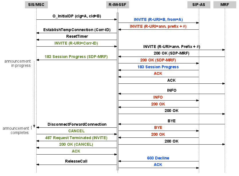
R-IM-SSF Protocol Translator 1.4.2 :: R-IM-SSF Protocol ...
SBC SIP-to-SIP Basic Call Processing Flow SBC SIP-to-SIP Basic Call Processing Flow The following diagram illustrates the SBC Edge basic SIP-to-SIP call processing. Figure : SBC Basic Call Processing Flow The call is received by the SBC. The Source IP addresses is matched against the Federated IP addresses contained in all the Signaling Groups (SG).

04. VoLTE SIP Call Flow – Mobile Originating (MO ...
Microsoft Teams call flows - Microsoft Teams | Microsoft Docs Call flows in various topologies. Illustrates the use of call flows in various topologies. For each topology, the section enumerates all supported flows and illustrates how these flows are used in several use cases. For each use case, it describes the sequence and selection of flows using a flow diagram. Teams with Express Route optimization.

FortiVoice Local Survivable Gateway Deployment Guide ...
Call flow diagrams - ibm.com The call flow diagram displays the sequence of messages that are sent between agents and servers. The SIP Modeling Toolkit provides some base classes that specify all the messages and responses specified in RFC 3261. The base classes can be user agents Session Initiation Protocols (SIPs), and so on.

A Basic SIP Call Flow | TelcoNotes
![SIP call flow diagram [10] | Download Scientific Diagram](https://www.researchgate.net/profile/Iwan_Putro2/publication/43649608/figure/fig2/AS:650497572741139@1532102115639/SIP-call-flow-diagram-10.png)
SIP call flow diagram [10] | Download Scientific Diagram
An Introduction to SIP Protocol: Definition, Features, & More
Call Flow Diagram :: SIP3 Documentation
SIP signalling- the registration process and setting up a SIP ...
VoIP Protocols: SIP Call Flow

SIP | Protocol Overview, Performance, Monitoring

SIP call session message flow | Download Scientific Diagram

Confluence Mobile - Documentation
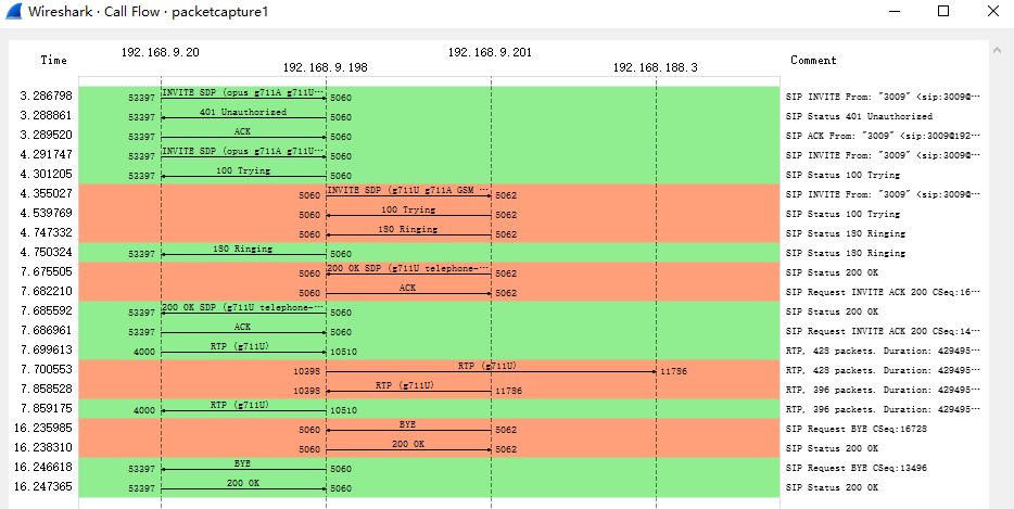
How to Analyze SIP Calls in Wireshark – Yeastar Support
BASICS about SIP
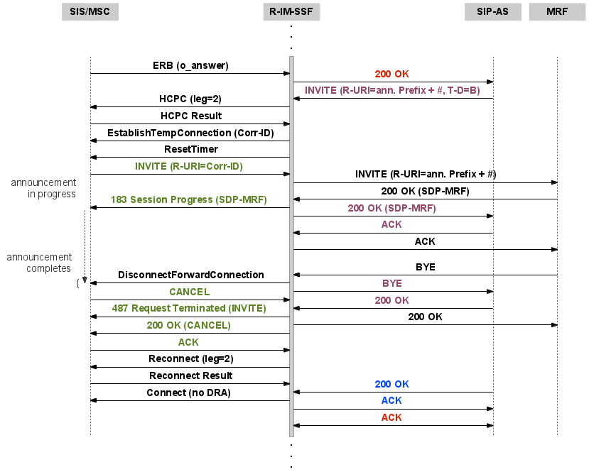
R-IM-SSF Protocol Translator 1.4.2 :: R-IM-SSF Protocol ...

SIP to SIPT/SIP-I Overview
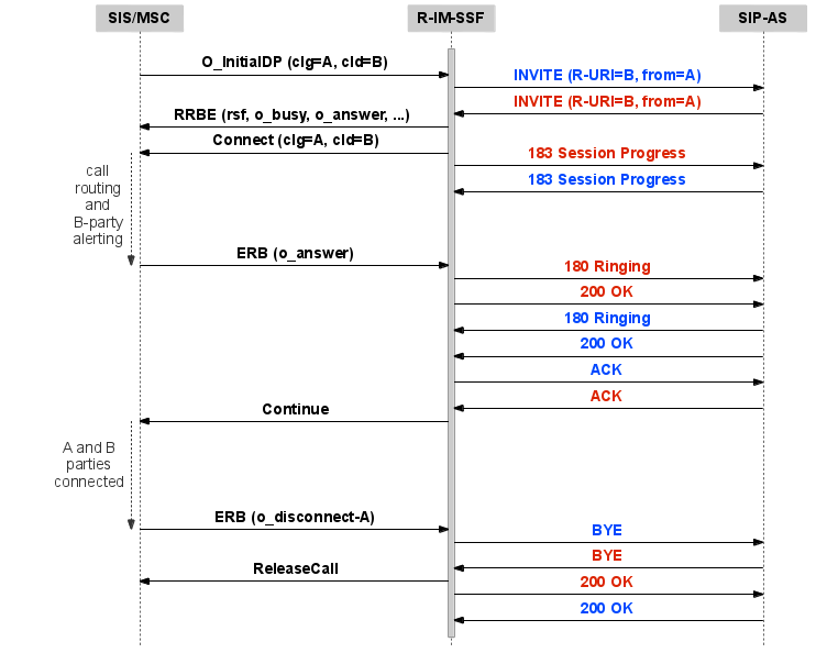
R-IM-SSF Protocol Translator 1.4.2 :: R-IM-SSF Protocol ...
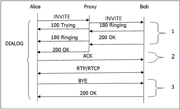
SIP - Basic Call Flow

When comparing the two call flows, which statement is true?

Call Transfer via SIP REFER | Twilio

Creating SIP call flow sequence diagrams from network traces
Cisco SIP IP Administrator Guide, Version 8.0 - SIP Call ...

Test bed architecture & SIP Call Flow | Download Scientific ...

4. Volte call flow - SIP Call Flow - IMS Call procedure

Confluence Mobile - Documentation
SIP Diagrams with Mermaid
SIP Tutorial: SIP to ISDN Q.931 Call Flow (Detailed ...
0 Response to "37 sip call flow diagram"
Post a Comment