40 consider the circuit in the diagram below, in which r = 11 ω.
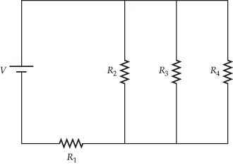
In the circuit diagram given below five resistances of 10 ... In the circuit diagram given below five resistances of 10 Ω, 40 Ω, 30 Ω, 20 Ω and 60 Ω are connected as shown to a 12 V battery. Calculate : (a) total resistance in the circuit. (b) total current flowing in the circuit. Answered: Consider the circuit in the following… | bartleby Question. Consider the circuit in the following diagram, where the resistances are R1 = 0.15R, R2 = 2R, R3 = 0.55R, and R4 = 3R, where R = 78 Ω. The circuit is connected to a V = 4.7 V source. (i) Input an expression for the equivalent resistance of the circuit in terms of R1, R2, R3, and R4. (ii) Input an expression using the Req and V for ...
Consider the following circuit diagram. If R1 = R2 = R3 ... Consider the following circuit diagram. If R 1 ... If the resistance is 15 Ω then the equivalent resistance between A and B will be - Medium. View solution > ... class 11. Oscillations Redox Reactions Limits and Derivatives Motion in a Plane Mechanical Properties of Fluids. class 12.
Consider the circuit in the diagram below, in which r = 11 ω.
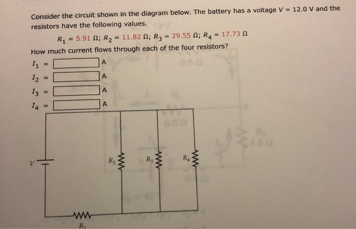
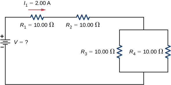
Solved Consider the circuit shown in the diagram below ... Consider the circuit shown in the diagram below. The battery has a voltage V = 12.0 V and the resistors have the following values.. R 1 = 1.86 Ω; R 2 = 3.72 Ω; R 3 = 9.30 Ω; R 4 = 5.58 Ω. How much current flows through each of the four resistors? consider the circuit shown in the diagram find the current ... formula of equivalent resistance in parallel and series' what is formula for Resistance in series and parallel Judge the equivalent resistance when the following are connected in parallel - (a) 1 Ω and 106Ω, (b) 1Ω and 103Ω and 106Ω. can you please answer this question fast. What is the power dissipated in resistor R 1 in the ... What is the power dissipated in resistor R 1 in the circuit shown in the diagram from PHYS 1120 at University of Colorado, Boulder
Consider the circuit in the diagram below, in which r = 11 ω.. PDF Frequency Response of Circuit - cpp.edu R L ω ω ω == + c R L ω= A Serial RL Circuit Result ECE 307-4 22 Frequency Response of a Circuit Example Define R and L values for a high pass filter with a cutoff frequency of 10KHz. Find |H(jω)|at 5 KHz Let We can't calculate R and L values independently. We can select R or L values then define the other RK=Ω1 c R L ω = 1000 15.9 2 ... PDF XII. AC Circuits - Worked Examples R R <>=< >=<ω>= (5.2) (c) If only switch 1 is opened, the current will pass through the generator, the resistor and the inductor. For this RL circuit, the impedance becomes 2222 11 L Z R XRω 2 == ++L (5.3) and the phase angle φ is tan 1 L R ω φ= − (5.4) Thus, the current as a function of time is 0 1 222 cos tan V L It t RL R ω ω ω ... PDF CIRCUITS WORKSHEET R - Livingston Public Schools 10) Determine the resistance of resistor R shown in the diagram. Questions 11 through 13 refer to the following: A 3.0-ohm resistor, an unknown resistor, R, and two ammeters, A 1 and A 2, are connected as shown at right with a 12-volt source. Ammeter A 2 reads a current of 5.0 amperes. 11) Determine the equivalent resistance of the circuit shown. PDF Circuit Circuit Circuit Analysis with Answers Basc your answers to questions 14 through 16 on the information and diagram below, showing all work including the equation and substituñon with units. A 50-ohm resistor, an unknown resistor R, a 120-volt source, and an ammeter are connected in a complete circuit.
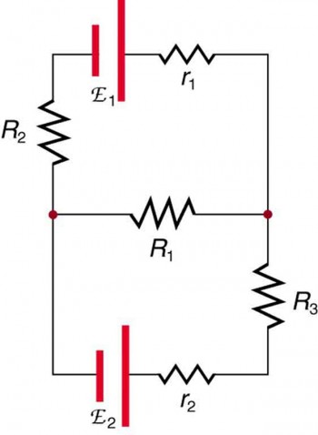
PDF Chapter 3 Nodal and Mesh Equations - Circuit Theorems Figure 3.86. Circuit for Problem 10 11. Use the superposition principle to compute the voltage in the circuit of Figure 3.87. Answer: Figure 3.87. Circuit for Problem 11 RLOAD 135 w 12 A 18 A 4 Ω 6 Ω 12 Ω 15 Ω + − 36 V RLOAD iN = 0R, N = 23.75 Ω 4 Ω 5 Ω iX 15 Ω 5iX a b v18A 1.12 V 12 A 24 A 18 A + − 10 Ω-1 4 Ω-1 6 Ω -1 8 Ω ... PDF Chapter11 Circuits - New Providence School District Questions 11-12 The above circuit diagram shows a battery with an internal resistance of 4.0 ohms connected to a 16-ohm and a ... 0.1 Ω (B) 10 Ω (C) 12 Ω (D) 120 Ω ... Consider the compound circuit shown above. The three bulbs 1, 2, and 3 - represented as resistors in the ... Consider the circuit in the diagram below. in which r = 11 ω. Consider the circuit in the diagram below, in which R = 11 ohm. (a) What is the resistance between points A and B? _____ Ohm(b) A 265-V emf is connected to the terminals A and B as shown above. In the circuit diagram given in fig. 12.10, suppose the ... In the circuit diagram given in fig. 12.10, suppose the resistors R 1 , R 2 and R 3 have the values 5 Ω, 1 0 Ω, 3 0 Ω respectively, which have been connected to a battery of 12V. calculate (a) the current through each resistor, (b) the total current in the circuit, and (c) the total circuit resistance.
Example 12.9 - If in Fig. 12.12, R1 = 10, R2 ... - teachoo If in Fig. 12.12, R 1 = 10 Ω, R 2 = 40 Ω, R 3 = 30 Ω, R 4 = 20 Ω, R 5 = 60 Ω, and a 12 V battery is connected to the arrangement. Calculate (a) the total resistance in the circuit, and (b) the total current flowing in the circuit. Example 12.8 - In the circuit diagram given in Fig. 12.10 ... In the circuit diagram given in Fig. 12.10, suppose the resistors R 1 , R 2 and R 3 have the values 5 Ω, 10 Ω, 30 Ω, respectively, which have been connected to a battery of 12 V. Calculate (a) the current through each resistor, (b) the total current in the circuit, and (c) the total circuit resistance. PDF PHYS-2020: General Physics II Course Lecture Notes Section IV Example IV-1. Consider the circuit shown below, where R1 = 3.00 Ω, R2 = 10.0 Ω, R3 = 5.00 Ω, R4 = 4.00 Ω, and R5 = 3.00 Ω. (a) Find the equivalent resistance of this circuit. (b) If the total power supplied to the circuit is 4.00 W, find the emf of the battery. + − E R1 R2 R3 R4 R5 Solution (a): We have to reduce this circuit in steps ... PDF Parallel Circuits -Key - Yola = __1.64 Ω__ 7. Consider the circuit at the right. a. There is a voltage drop of __6__ V across each 2- resistor. ... 11. A 2-Ω and a 4-Ω resistor are connected in a parallel circuit. The current through the 4-Ω resistor will ... Use the diagram below at the right in order to answer questions.
Kirchhoff's Rules | Physics
a circuit is shown in the diagram given below find a the ... A circuit is shown in the diagram given below. Find (a) the value of R. (b) the reading of the ammeter. (c) the potential difference across the terminals of the battery.

DC Motor Tutorial - Motor Calculations for Coreless Brush DC ...
Question with solution (circuit diagram) - My Electrical Note question with solution circuit diagramTweet you may want to read basic electrical Question 1: The value of current (I) flowing in the 1 Ω (ohm) resistor in the circuit shown in the figure below will be: We will solve this question using both KVL (kirchoff voltage law) and KCL (kirchoff current law): Applying KVL in…
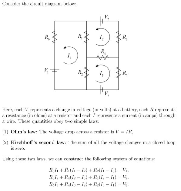
Consider the circuit diagram below 尼 I. R, R, Here, | Chegg.com
Solved Consider the circuit shown in the figure below ... Transcribed image text: Consider the circuit shown in the figure below. (Let R = 32.0 Ω.) 25.0 V 10.0 Ω 10.0 Ω ๕罷 5.00 Ω (a) Find the current in the 32.0-Ω resistor. (b) Find the potential difference between points a and b

Consider the circuit shown in the diagram. Find the current ...
Solved Consider the circuit given below, where R= 11 Ω ... Consider the circuit given below, where R= 11 Ω. 14V 14Ω 1 A 3 A References eBook &Resources Section Break Difficulty: Medium Learning Objective: Under can lead to greatly simplif value: 10.00 points Find the Thevenin equl f the crcui (Round the tnal answe to twe decimal places) TH= VTH-
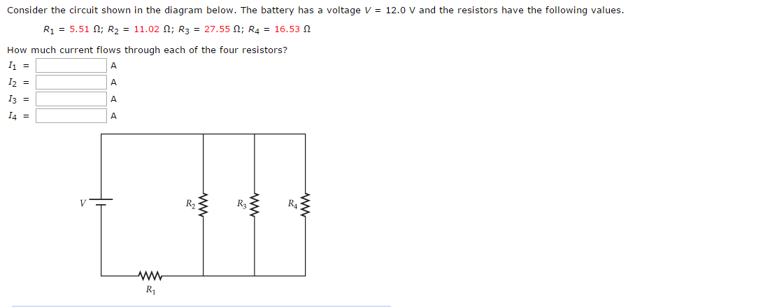
Solved Consider the circuit shown in the diagram below. The ...
Solved Consider the circuit shown in the diagram below ... Consider the circuit shown in the diagram below. The battery has a voltage V = 12.0 V and the resistors have the following values. R1 = 4.12 Ω; R2 = 8.24 Ω; R3 = 20.60 Ω; R4 = 12.36 Ω How much current flows through each of the four resistors? I1 = A I2 = A I3 = A I4 = A; Question: Consider the circuit shown in the diagram below. The battery ...
consider the circuit shown in the diagram find the current in ...
Physics _ Chap 13 Flashcards - Quizlet The total resistance of the circuit is R=Rbt+Rbulb=3.5 Ω + 19 Ω R=22.5 Ω The current through the 19-Ω resistor is I=VR=6 V22.5 Ω I=0.2667 A The voltage difference ΔVbulb across the 19-Ω resistor is calculated as follows: ΔV=5.0667 V

Lesson Explainer: Analyzing Combination Circuits | Nagwa
Solved Consider the circuit shown in the diagram below ... Consider the circuit shown in the diagram below. The battery has a voltage V = 12.0 V and the resistors have the following values. R1 = 2.32 2; R2 = 4.64 2, R2 = 11.60 2; R = 6.96 2 How much current flows through each of the four resistors? w RA ; Question: Consider the circuit shown in the diagram below. The battery has a voltage V = 12.0 V ...
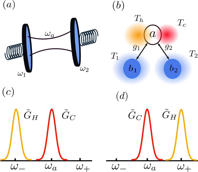
Ground-state cooling of mechanical resonators by quantum ...
Answered: In the diagram below, R1=30 Ω, R2=13 ... - bartleby In the diagram below, R 1 =30 Ω, R 2 =13 Ω, R 3 =40 Ω, and R 4 =30 Ω. At first, a segment with R 4 is disconnected from the circuit and then it is connected as shown. Find the equivalent resistance before the R 4 is attached: R eq i = Ω. Find the current passing through the R 3 resistor before the R 4 is attached: I i = A. Find the equivalent resistance after the R 4 is attached:

Smith chart - Wikipedia
Deduce the expression for the equivalent ... - Sarthaks Consider the following parallel circuit shown below: Let I 1, I 2 and I 3 be the current flow through the resistor R 1, R 2 and R 3 connected in parallel. Using Ohm's law, current through each resistor is. I 1 = V/R 1, I 2 = V/R 2 and I 3 = V/R 3. Let their equivalent resistance be R p then. V = I R p ⇒ I = V/R p. Total current through the circuit is
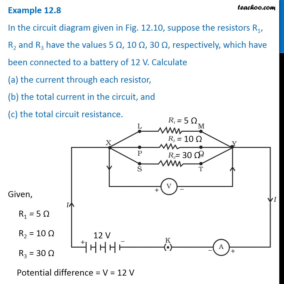
Example 12.8 - In the circuit diagram given in Fig. 12.10 ...
Answered: Required information Consider the… | bartleby Question. Consider the circuit diagram given below. where R1 = 4.40 Ω, R2 = 4.00 Ω, and R3 = 2.10 Ω. Find the unknown emf ε1 in the circuit. Find the unknown emf ε2 in the circuit. Transcribed Image Text: ! Required information Consider the circuit diagram given below. 195mA R1 2.000 50.0 1.00 V R2 where R = 4.40 Q, R2 = 4.00 0, and R3 = 2 ...

Theory of solar cells - Wikipedia
What is the power dissipated in resistor R 1 in the ... What is the power dissipated in resistor R 1 in the circuit shown in the diagram from PHYS 1120 at University of Colorado, Boulder
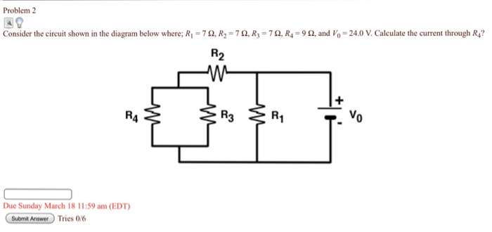
Solved Problem 2 Consider the circuit shown in the diagram ...
consider the circuit shown in the diagram find the current ... formula of equivalent resistance in parallel and series' what is formula for Resistance in series and parallel Judge the equivalent resistance when the following are connected in parallel - (a) 1 Ω and 106Ω, (b) 1Ω and 103Ω and 106Ω. can you please answer this question fast.
Consider the circuits shown. The resistance connected between ...
Solved Consider the circuit shown in the diagram below ... Consider the circuit shown in the diagram below. The battery has a voltage V = 12.0 V and the resistors have the following values.. R 1 = 1.86 Ω; R 2 = 3.72 Ω; R 3 = 9.30 Ω; R 4 = 5.58 Ω. How much current flows through each of the four resistors?
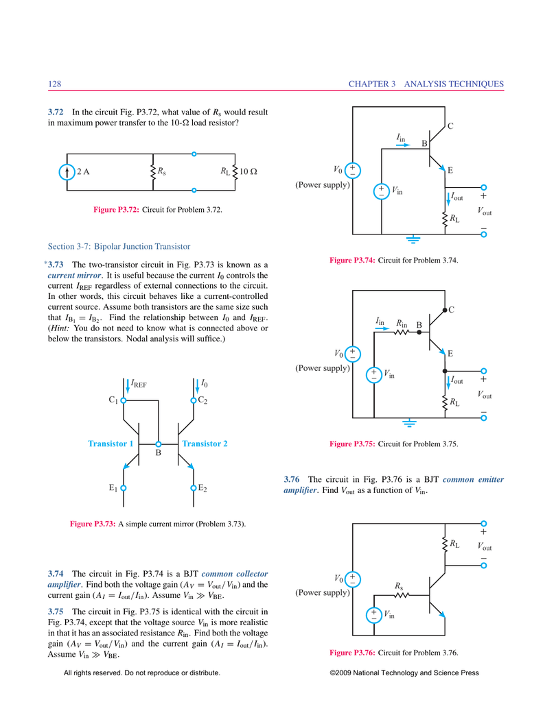
2 A RL Rs 10 Ω I0 C2 E2 C1 E1 B Transistor 2 Transistor 1 C E
Solved Consider the circuit shown in the diagram below. The ...

Consider the circuit in the figure. Find the current in the ...

Kirchhoff's Rules – University Physics Volume 2
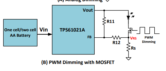
TPS61087: LED PWM dimming using TPS61087 - Power management ...
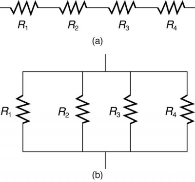
Resistors in Series and Parallel | Physics II
![Best Answer] consider the following circuit diagram if R1 ...](https://hi-static.z-dn.net/files/dcb/bd0ce4cfe81babda43d4358544bca9c7.jpg)
Best Answer] consider the following circuit diagram if R1 ...

Wheatstone Bridge Circuit | Strain Gauge | HBM

In the circuit shown, the current through the 4 Omega ...

Consider the circuit diagram as given below. If R1=R2=R3=R4 ...

Lakhmir Singh Physics Class 10 Solutions For Chapter 1 ...

Phasor - Wikipedia
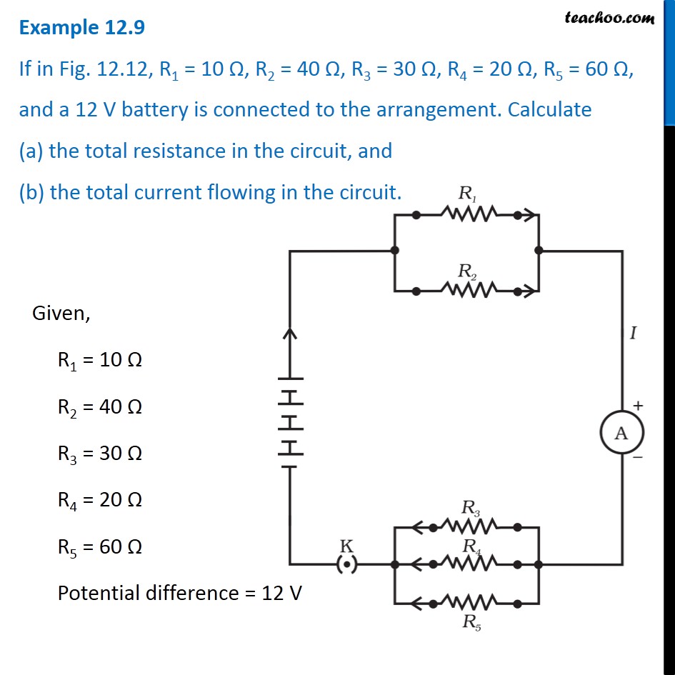
Example 12.9 - If in Fig. 12.12, R1 = 10, R2 = 40, R3 = 30 ...

Parallel RLC Circuit and RLC Parallel Circuit Analysis
Electric field control of radiative heat transfer in a ...
Solved Consider the circuit shown in the diagram below. The ...

Active topolectrical circuits | PNAS
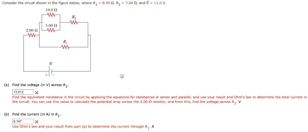
Solved Consider the circuit shown in the figure below, where ...

Consider the following circuit diagram. If R1 = R2 = R3 = R4 ...

Circuits Flashcards | Quizlet

Consider the circuit shown in the figure below - YouTube

Find the equivalent resistance in the diagram below: | Study.com

Consider the circuit shown in the figure below
Resistors in Series and Parallel – University Physics Volume 2
Chapter 11 Circuits
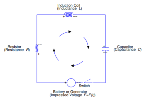
6.3: The RLC Circuit - Mathematics LibreTexts

C OMBINATION C IRCUITS Lesson 7. C OMBINATION CIRCUITS ...
0 Response to "40 consider the circuit in the diagram below, in which r = 11 ω."
Post a Comment