40 phase lock loop block diagram
What Is a Phase-Locked Loop (PLL)? - NI A phase-locked loop (PLL) is a feedback circuit designed to allow one circuit board to synchronize the phase of its on board clock with an external timing signal. PLL circuits operate by comparing the phase of an external signal to the phase of a clock signal produced by a voltage controlled crystal oscillator (VCXO). (PDF) Design Phase Locked Loop Accuracy towards ... Design of the Multiple Rate PLL The design will now be described in more detail with reference to the accompanying figures, in which: Figure 1 is a block diagram of a high gain low jitter PLL with a multiple rate digital loop filter. The phase locked loop frequency synthesizer shown in Figure 1 (a) comprises a stable crystal oscillator, for ...
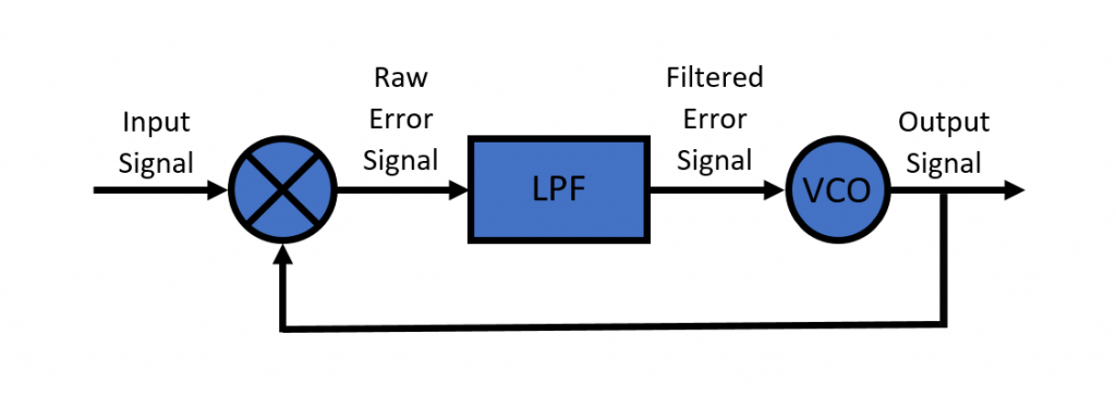
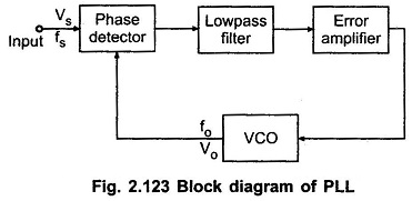
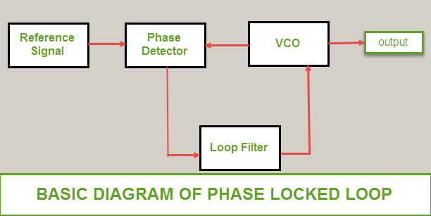
Describe the basic block diagram of the phase locked loop ... A phase locked loop is basically a closed loop system designed to lock the output frequency and phase to the frequency and phase of an input signal. They are used in applications such as frequency synthesis, frequency modulation/demodulation, AM detection, tracking filters, FSK demodulator, tone detector etc.
Phase lock loop block diagram
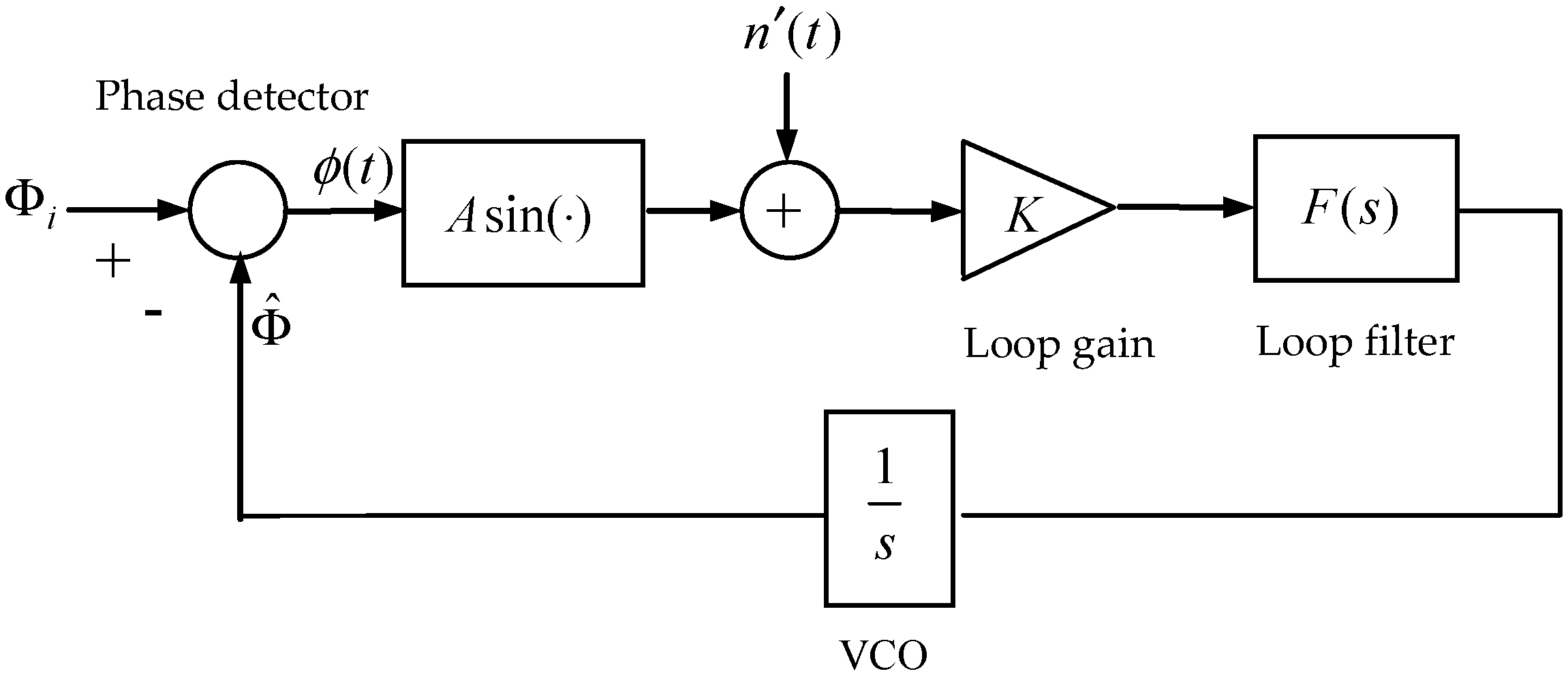
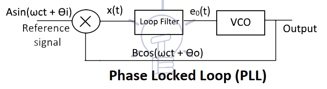
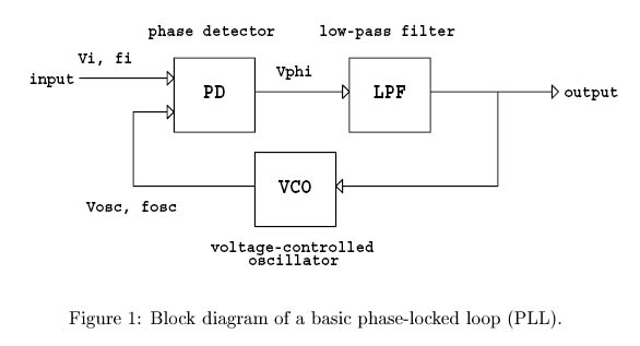
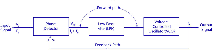
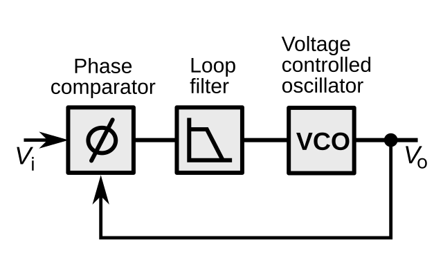
Phase Locked Loop Operating Principle and Applications Block Diagram And Working Principle Of PLL. The phase-locked loop consists of a phase detector, a voltage controlled oscillator and, in between them, a low pass filter is fixed. The input signal 'Vi' with an input frequency 'Fi' is conceded by a phase detector. Basically the phase detector is a comparator that compares the input ... Phase Locked Loop IC - Tutorialspoint Phase Locked Loop (PLL) is one of the vital blocks in linear systems. It is useful in communication systems such as radars, satellites, FMs, etc. This chapter discusses about the block diagram of PLL and IC 565 in detail. Block Diagram of PLL. A Phase Locked Loop (PLL) mainly consists of the following three blocks −. Phase Detector; Active ... (a) Sketch the block diagram of a phase locked loop ... Electrical Engineering questions and answers. (a) Sketch the block diagram of a phase locked loop FM demodulator with the linearizing assumption that sin (0) = 0. Your block diagram should show the input phase Oi (t) A Oi (s) of the received FM passband signal, the output phase Oo (t) < Oo (s) of the voltage control oscillator (VCO), the loop ...
Phase lock loop block diagram. PDF ECE 440 Overview of Phase Lock Overview of Phase Lock J. V. Krogmeier Purdue University, West Lafayette Friday April 24, 2022. From TI Application Report (Sept. 2002) From TI Application Report (Sept. 2002) From Fairchild Datasheet (Oct. 2003) From Phillips Datasheet (Nov. 1997) Standard PLL Block Diagram" VCO phase H loop(f) PDF Digital Phase Locked Loop - Electrical & Computer Engineering 2.1 Phase Locked Loops (PLL) A phase locked loop is a device which generates a clock and sychronizes it with an input signal. The input signal can be data or another clock. The best known application of PLLs is clock recovery in communication. When an signal of a known frequency is being recieved often a Phase-locked loop - Wikipedia A phase-locked loop or phase lock loop (PLL) is a control system that generates an output signal whose phase is related to the phase of an input signal. There are several different types; the simplest is an electronic circuit consisting of a variable frequency oscillator and a phase detector in a feedback loop.The oscillator generates a periodic signal, and the phase detector compares the ... What are Phase-Locked Loops (PLL)? Definition, Block ... Definition: Phase-locked loops are the circuits used to maintain synchronization between input and output frequency of oscillator circuits by comparing the difference in phase of the two signals.With the evolution of IC, it has emerged as the basic building block of electronic circuits. Phase-locked loops are abbreviated as PLL and are basically a feedback circuit comprising of a phase ...
PDF Phase Locked Loop Control of Inverters in a Microgrid C. Three-phase PLL design A block diagram displaying the functional components of a generic PLL is shown in Figure 3. For small deviations, standard simplifying assumptions [7] allow the PLL to be modeled according to the linear block diagram of Figure 4, where t is the phase of the measured voltage and p is the phase estimate given by the PLL. Voltage controlled oscillator circuit using LM566 VCO IC This output frequency is given to the phase detector via a divide by N counter which divides the output frequency by a certain number N and gives it to the phase detector. This entire process works in a loop hence it is called a phase lock loop. LM567 is a PLL that is used as a tone decoder. PDF PHASE LOCKED LOOP - idc-online.com · Phase detector 1 is used in applications that require zero frequency and phase difference at lock. · Phase detector 2, if quadrature lock is desired, when detector 1 is used in the main loop, detector can also be used to indicate whether the main loop is in lock or out of lock. R Reference The phase locked loop (PLL) block diagram. | Download ... Download scientific diagram | The phase locked loop (PLL) block diagram. from publication: PLL Based Digital Adaptive Filter for Detecting Interharmonics | Studies on the PLL (phase locked loop ...
Phase-Locked Loops - MATLAB & Simulink Phase recovery methods and phase-locked loops. You specify the filter's transfer function in the block mask using the Lowpass filter numerator and Lowpass filter denominator parameters. Each of these parameters is a vector that lists the coefficients of the respective polynomial in order of descending exponents of the variable s. PDF Phase Locked Loop Circuits - UC Santa Barbara Ve-max = ± KD π/2 When the phase detector output voltage is applied through the loop filter to the VCO, ∆ωout - max = ± KV π/2 = ωL (lock range) where KV = KO KD, the product of the phase detector and VCO gains. This is the frequency range around the free running frequency that the loop can track. Phase Lock Loop Block Diagram - Google Search A phase-locked loop (PLL) is a circuit with a voltage or current driven oscillator that constantly changes to lock on to the frequency of the input signal. The PLL can be used to: Generate signals Modulate Demodulate Reconstitute a signal producing less noise Multiply & Divide a frequency PLL's are consistently used in wireless communication, usually signals carried are using FM, AM, or, PM ... Phase Locked Loop (PLL) - its Operation, Characteristics ... The phase locked loop or PLL is an electronic circuit with a voltage controlled oscillator, whose output frequency is continuously adjusted according to the input signal's frequency. A Phase locked loop is used for tracking phase and frequency of the input signal. It is a very useful device for synchronous communication.
Applied Sciences | Free Full-Text | Investigation of Phase ...
Phase Lock Loop basics, Block Diagram & working in ... In this video, i have explained Phase Lock Loop by following outlines:1. Phase Lock Loop2. Basics of Phase Lock Loop3. Need of Phase Lock Loop 4. Block Diagr...
Phase Lock Loop – Explained | RAYmaps
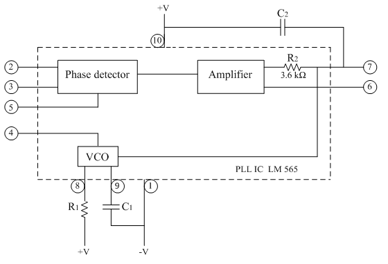
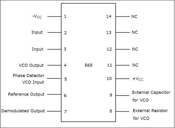
565 Phase-Locked Loop: A Suitable IC for Linear Systems Block diagram of LM565 PLL. 565 Phase-Locked Loop: Block diagram explanation. The block diagram of IC 565 includes a V CO in a feedback loop, an amplifier, a low pass filter, and a phase detector.. The phase-locked feedback loop has no internal connection. Hence, you'll need to externally connect pin4 (V CO output) to pin5 (phase comparator input).. When applying IC565 in frequency ...

Explain PLL using block diagram of IC 565
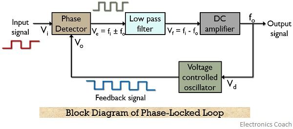
Phase Locked Loops, block diagram,working,operation,Design ... PLL Block Diagram. The block diagram of a basic PLL is shown in the figure below. It is basically a flip flop consisting of a phase detector, a low pass filter (LPF),and a Voltage Controlled Oscillator (VCO). Block Diagram - Phase Locked Loops. The input signal Vi with an input frequency fi is passed through a phase detector.

ClassECE4332Fall15GroupPLL - UVA ECE & BME wiki
Phase Locked Loop - an overview | ScienceDirect Topics The block diagram of a phase locked loop. (11.35) f ref = f d = F out N. or (11.36) F out = N f ref. Since the divisor N is easy to change in practice, a wide range of frequencies can be generated from a single reference. These frequencies have the accuracy and long-term stability of the original reference.
Phase Locked Loop (PLL) - its Operation, Characteristics ...
PDF Phase Locked Loops (PLL) and Frequency Synthesis Phase Locked Loop Block Diagram!" ÖN Ref Div Loop Filter VCO Phase Locked Loops (PLL) are ubiquitous circuits used in countless communication and engineering applications. Components include a VCO, a frequency divider, a phase detector (PD), and a loop lter. Niknejad PLLs and Frequency Synthesis

Phase Locked Loop (PLL)
Phase locked loop - SlideShare BLOCK DIAGRAM of PLL PHASE DETECTOR LOW PASS FILTER VOLTAGE CONTROLLED OSCILLATOR (VCO) Input Output Ve Vc Vo , foVi , fi Feedback Path A BASIC PHASE LOCKED LOOP 4 5. PHASE DETECTOR • The two inputs to a phase detector or comparator are the input voltage Vi, at frequency fi and the feedback voltage from a Voltage controlled oscillator (VCO ...
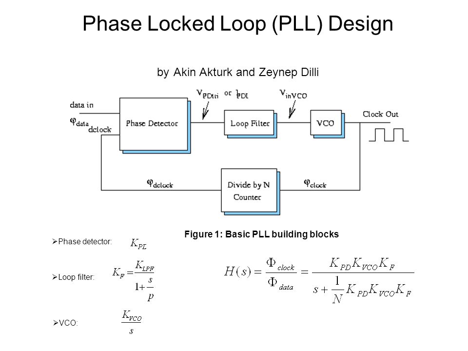
Phase detector: Loop filter: VCO: Phase Locked Loop ...
PDF CD4046B Phase-Locked Loop: A Versatile Building Block for ... 4 CD4046B Phase-Locked Loop: A Versatile Building Block for Micropower Digital and Analog Applications 3 CD4046B PLL Technical Description Figure 2 shows a block diagram of the CD4046B, which has been implemented on a single monolithic integrated circuit. The PLL structure consists of a low-power, linear VCO and two
Lab_6,7,8) Phase Lock Loop - D.Son978
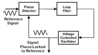
Phase Locked Loop Tutorial - Block Diagrams - Electronics ... Phase Locked Loop Tutorial - Block Diagrams - Electronics Circuit and Tutorials - Hobby Science Projects - The Phase Locked Loop (PLL) synchronizes a local oscillator with a remote one. This ensures that the local oscillator is at the same frequency and in phase with the remote one.

Phase-Locked Loop (PLL) Fundamentals | Analog Devices
PLL Working | Phase Locked Loop Working operation The figure-1 depicts Block Diagram of Phase locked loop i.e. PLL Circuit in order to explain PLL working operation. PLL mathematical equation can be expressed as Fo = Fr * N , Hence Fo can be changed to different values within the range in either of the following ways. 1. keeping Fr fixed and varying N 2. Keeping N fixed and varying Fr.
Phase Locked Loop Working Principle | PLL block diagram ...
PDF Lecture 430 - Phase-locked Loops Function of a phase-locked loop is to lock the frequency of a VCO to an input frequency. Block diagram: Phase Frequency Vo Detector (PFD) LPF VCO Input Frequency fin fosc MPLL09 Output Voltage Components: • Phase/frequency detector outputs a signal that is proportional to the difference between

Phase Locked Loop - an overview | ScienceDirect Topics
Phase-Locked Loop (PLL) Fundamentals - Analog Devices For phase-locked loop circuits, the bandwidth of the low-pass filter has a direct influence on the settling time of the system. The low-pass filter is the final element in our circuit. If settling time is critical, the loop bandwidth should be increased to the maximum bandwidth permissible for achieving stable lock and meeting phase noise and ...

Describe the basic block diagram of the phase locked loop (PLL).
(a) Sketch the block diagram of a phase locked loop ... Electrical Engineering questions and answers. (a) Sketch the block diagram of a phase locked loop FM demodulator with the linearizing assumption that sin (0) = 0. Your block diagram should show the input phase Oi (t) A Oi (s) of the received FM passband signal, the output phase Oo (t) < Oo (s) of the voltage control oscillator (VCO), the loop ...

Block diagram of the phase-locked loop circuit. | Download ...
Phase Locked Loop IC - Tutorialspoint Phase Locked Loop (PLL) is one of the vital blocks in linear systems. It is useful in communication systems such as radars, satellites, FMs, etc. This chapter discusses about the block diagram of PLL and IC 565 in detail. Block Diagram of PLL. A Phase Locked Loop (PLL) mainly consists of the following three blocks −. Phase Detector; Active ...
Phase-Locked-Loop | Mini Projects | Electronics tutorial ...
Phase Locked Loop Operating Principle and Applications Block Diagram And Working Principle Of PLL. The phase-locked loop consists of a phase detector, a voltage controlled oscillator and, in between them, a low pass filter is fixed. The input signal 'Vi' with an input frequency 'Fi' is conceded by a phase detector. Basically the phase detector is a comparator that compares the input ...
All Digital PLL

Phase Lock Loop - Digital Control and Systems - Timothy Walters

Simulink Exercises for "Digital Communications: A Discrete ...

Phase-locked loops in an IC-based clock distribution system ...

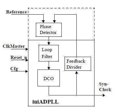
General block diagram of ADPLL Beginning of all digital phase ...

Circuit/ Block Diagrams Archives - Page 16 of 25 - Electronic ...

Phase Locked Loop Operating Principle(हिन्दी )
Phase Locked Loop Operating Principle and Applications

The Working Of Phase Detector In PLL - ADSANTEC

Moku:Pro: Implementing a Phase Locked Loop - Liquid Instruments

Clock Generation Using PLL Frequency Synthesizers | DigiKey
Phase Locked Loop Operating Principle and Applications
Optical Phase Locking techniques: an overview and a novel ...

Frequency and phase locked loops - EDN
Extremely Coherent Microwave Emission from Spin Torque ...

Simulating phase locked loops with MATLAB

Phase Locked Loop – Analog/RF IntgCkts
PLL IC 565 | Analog-integrated-circuits || Electronics Tutorial
Phase-locked loop - Wikipedia
Phase Locked Loops
What are Phase-Locked Loops (PLL)? Definition, Block Diagram ...
Phase Locked Loop IC
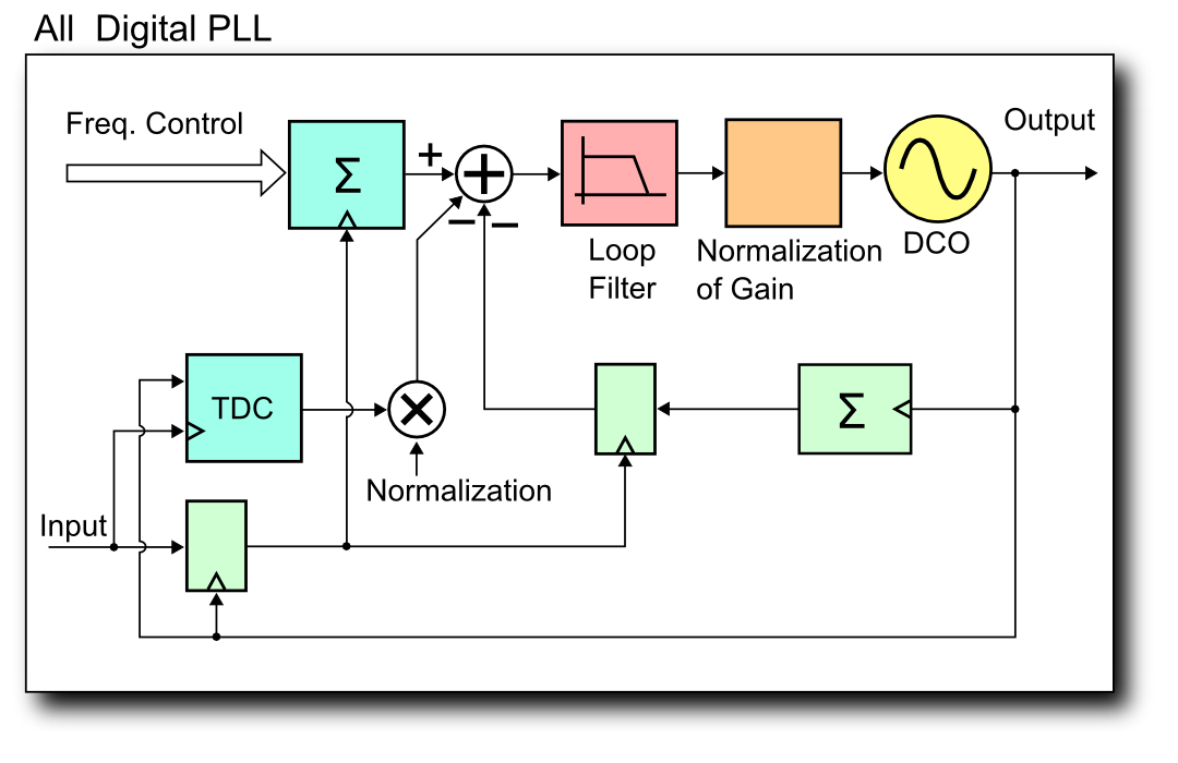
File:All Degital PLL (block diagram-2).PNG - Wikimedia Commons

Phase Locked Loop System Working and Applications

PLL Phase Locked Loop: How it Works » Electronics Notes

Phase-locked loop - Wikipedia
0 Response to "40 phase lock loop block diagram"
Post a Comment