37 scully system wiring diagram
PDF Scully ST-47 Groundhog Technical Manual Technical Manual ST-47 Series Self-Proving Vehicle Grounding Veri˜cation System Scully Signal Company 70 Industrial Way, Wilmington, MA 01887, USA • 800-272-8559 • sales@scully.com • ST-47 Groundhog- Technical Manual Table of Contents General 5. 1.1 Purpose of Equipment 1.2 ST-47 Normal Operation bugs.openjdk.java.net › browse › JDK-8141210[JDK-8141210] Very slow loading of JavaScript file with ... FULL PRODUCT VERSION : java version "1.8.0_66" Java(TM) SE Runtime Environment (build 1.8.0_66-b17) Java HotSpot(TM) 64-Bit Server VM (build 25.66-b17, mixed mode ...
Support/Resources - Scully Signal POLICIES Conflict Minerals Statement Scully Ordering Terms and Conditions Scully Website Terms and Conditions DOCUMENTATION Storage Tank Equipment ST-15 WX Datasheets: ST15WX_US ST15WX_International ST15WX_French ST15WX_German ST15WX_Russian ST15WX_Spanish ST15WX_Portuguese Manuals: ST15 WX_Manual Safety Manual: ST15WX_Safety Manual SP-O Single Sensor Mounting Holder…
Scully system wiring diagram
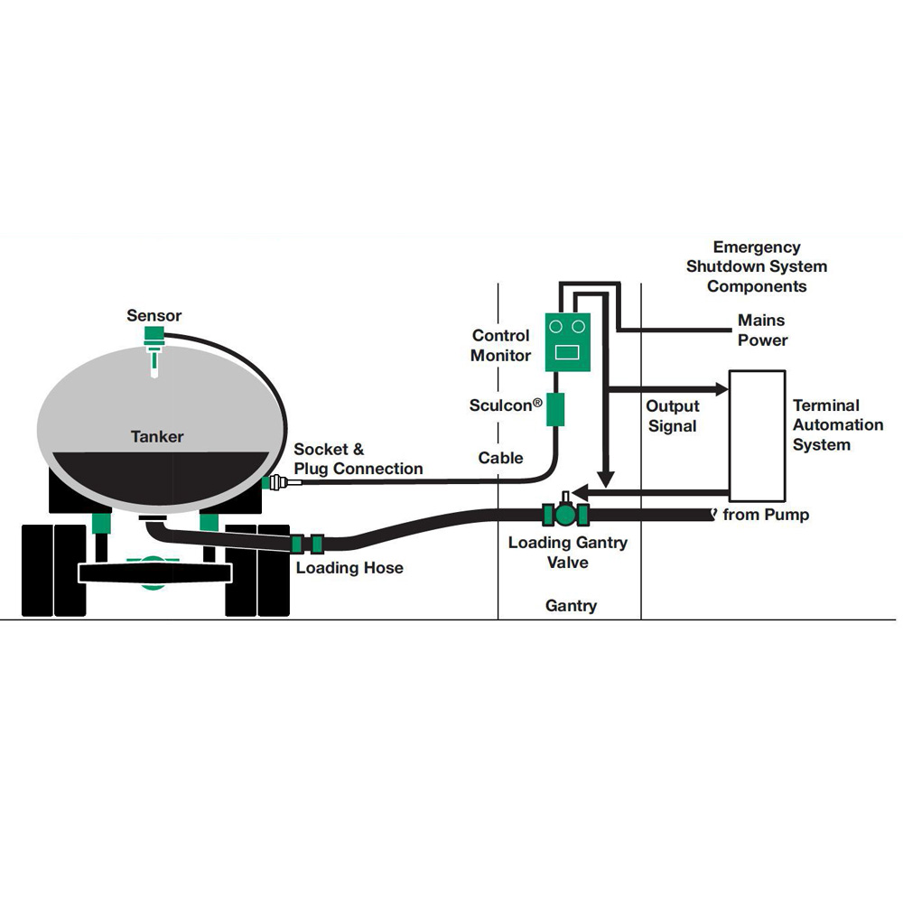
IntelliCheck®2 - Scully Signal For kits that include a Ground Bolt, T.I.M.®, Ground Bolt, T.I.M.® Truck ID Module, and Duo Cept™ Socket in the System Kit, call Scully for part numbers at 1-800-272-8559 or sales@scully.com. OVERFILL ONLY - 2-Wire System Kits › home › goods_maker[코릭스] AC/DC Power Supply, Modular Programmable AC/DC Power System: Ametek Rotron: Fan, Blowers, Thermal Management System: Ametek Solidstate Controls Inc: Industrial-Grade PWM UPS Systems & Power Inverter, Module: Ametel u.s gauge: Gauge: AMF Andreas Maier GmbH & Co. KG: Magnetic Clamping, Positioning System, Zero-Point System: AMG-Pesch GmbH PDF Scully Groundhog LINE The Scully Groundhog is a self-proving grounding system for maximum safety in loading operations. The system consists of a rack mounted control monitor with two system operation methods. It can operate in conjunction with your existing Scully Overfill Prevention System or as an independent unit.
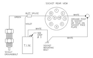
Scully system wiring diagram. Scully Green Thermistor Plug & Coiled Cord w/ 4 J-Slot ... Scully plugs are made of heavy duty molded polyurethane with stainless steel contacts. Scully plugs and cables are the product of years of industry experience and offer durable, efficient operation. 16 gauge, color coded & numerically labeled conductors for easy hook up & troubleshooting. PDF Liquip Sales Pty Limited Engineering Department 13 Hume ... Max 2 amp each @ 24Vdc. 9 Monitor to overfill probes 10 core overall screened, conductor size minimum 1.5mm2or 18AWG Refer to system wiring diagrams 10 Monitor to truck plug For TP104 2 wire system, use 10 core overall screened. For TP103 5 wire system, use 5 core overall screened. Both cases minimum conductor size of each core is 1.5mm2or 18AWG Scully System Wiring Diagram - Wiring Diagram Electronic Component Scully Signal Co Wiring Diagram Circuit Ground Png 554x900px Vdc001403 User Manual 8 Scully Signal 60982 St35 Revk Final For Print Ft208 Checkmate System With Retain And 5 Wire Manualzz Vdc001403 User Manual 8 Scully Signal Installation Instructions Untitled Scully St 47 Series Technical Manual Pdf Manualslib PDF Scully ST-47C Groundhog The Power terminals are marked E, N & L, also shown in wiring diagram. NOTE: The ST-47C Control Module is protected by a ˜eld replaceable 1A high interrupt capacity fuse in the enclosure. The fuse (F1) is located next to the terminal strip on metal bracket. 2.2.2 Enclosure Earth (Ground) Connection
play.google.com › store › booksBooks on Google Play The problem is your system. Bad habits repeat themselves again and again not because you don't want to change, but because you have the wrong system for change. You do not rise to the level of your goals. You fall to the level of your systems. Here, you'll get a proven system that can take you to new heights. PDF Scully Intellitrol Technical Manual Scully CivaCommand Smart Tank System Scully Intellitrol Technical Manual 61286 Intellitrol RevH FOR PRINT Scully - Setting Standards in Safety and Dependability since 1936. 61286 Intellitrol RevH FOR PRINT - Scully The Intellitrol is Scully's most advanced loading rack monitoring system. The Intellitrol was recently PDF Installation Instructions API 5 wire FT101 sensors. FloTech recommends wiring the sensors to the FT208 Monitor using FT404 11 conductor cable for up to 8 compartment systems. FloTech FT404 cable is color coded to ease installation and troubleshooting. A color coded wiring schematic is provided in the back of this manual. TB5 Socket Connections VDC001403 User Manual 8 Scully Signal Cut and place 1.5" of self sealing heat shrink tube over one end of sensor wire. 3. Strip off 1/ " of insulation from the VDC white wire. Mt the stripped VDC wire together with one of the sensor wire. 4. Crimp a butt splice connector onto the twisted wires. Crimp the other side of the connector onto the other stripped sensor wire. 5.
› en_us › aboutLegal - Trend Micro Global Business Software and Appliance Agreement (English) Welterweiter Vertrag Uber UnternehmensSoftware und/oder Gerate (German) Contrato de Licencia Global de Uso de Software y/o Dispositivos Trend Miro (Spanish) PDF 8460SRC Replacement Chassis for Scully ST-6 and Biclops ... Scully ST-6 or Biclops®internal chassis. The 8460SRC provides API compatible operation to all API thermistor and optic overfill systems. The 8460SRC replacement chassis requires simple hand tools and makes use of existing API plug, cord, and wiring connections. The 8460SRC also provides upgrade features including PDF Scully Load Anywhere System Scully Load Anywhere System Setting New Standards In Safety Scully Signal Company, 70 Industrial Way, Wilmington, MA 01887 U.S.A. Tel (617) 692-8600, Fax (617) 692-8620 Scully Load Anywhere®System Complete Overfill Prevention Loading Rack Compatibility Featuring Dynacheck®- Automatic and Continuous Self-Checking Circuitry Troubleshooting Ground Faults at the Loading Rack - Scully A ground fault may occur for one or more reasons, from a problem at the rack or the trailer. These issues can range from a loose socket on the trailer to a bad cable on the load rack. Below are some graphics, describing what you should look for while trouble shooting. 1. Broken Wire in the Plug and Cable.
OVERFILL PREVENTION – Kalymnos Fuel Engineering
Get to Know the Scully ST-47 Groundhog The Scully Ground Bolt's sensing lead is wired to the Scully Overfill Prevention Socket. Scully is the only company on the market that offers you a complete, integrated overfill prevention and vehicle grounding system for maximum safety in your loading operations. Don't use a system that's easily cheated.

Support/Resources - Scully Signal
Scully Thermistor Wiring Diagram - Wiring Diagram Scully Thermistor Wiring Diagram. By Admin | November 6, 2017. 0 Comment. Scully thermistor socket acme fluid handling untitled 28 checkmate system with retain and overfill manualzz installation instructions real world solutions training pdf free sockets truck mounted prevention connectors ft208 5 wire support resources signal maintenance ...

Support/Resources - Scully Signal
PDF Fault-finding, Tanker overfill protection 2 wire system. 4 Scully Optical 6.5 to 9.5 6.5 to 9.5 5 Scully Elec. Dummy 4.5 to 7.0 4.5 to 7.0 Compartment 3 has the higher voltage reading out of the three (3) Scully optical probes, so it is replaced and that fixes the problem. The probe is not necessarily faulty, the monitor channel many need an adjustment or there was a poor wiring connection in the tanker.

SCULLY - OVERFILL AND GROUND |
Intellitrol®2 - Scully Signal Refer to diagram on Intellitrol FM data sheet #67247: Sensor Inputs: Up to 8 Scully two-wire optic/thermistor sensors (6 or 8 channels) or 15 five-wire optic sensors (maximum). Automatic detection of two-wire vs. five-wire sensors. Three-wire, high-temperature thermistor sensors are not supported. Ground Verification Inputs:

SCULLY- TANK TRUCK- Featuring Dynacheck® Self-Checking Circuitry
Scully Wiring Diagram - Free PDF File Sharing The Scully tester operates by supplying about 11 volts to the red probe wires, ... The above diagram shows the basic wiring diagram of a retain/overfill IntelliCheckTM [Filename: 609_u0026_610_Operations_Manual.pdf] - Read File Online - Report Abuse Instruction Manual 10158 interchangeable with Scully and Civacon socket bodies. ...
Section 5 Overfill Protection
Scully System Wiring Diagram Database Scully System Wiring Diagram from fccid.io Print the cabling diagram off in addition to use highlighters to be able to trace the routine. When you employ your finger or even the actual circuit together with your eyes, it may be easy to mistrace the circuit. A single trick that I 2 to print the same wiring picture off twice.
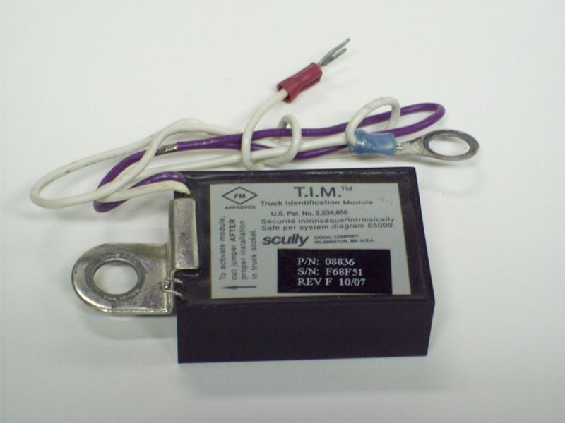
SCU08836
Home - Scully Signal Scully's inhouse manufacturing is vertically integrated with our own machine shop, diecast, electronic, and mechanical assembly. We have access to components and plenty of production capacity. Scully's core systems include—but are not limited to—overfull prevention, static ground proving, retained product monitoring, and oil delivery.

Scully 08836 T.I.M.® for V.I.P. System Compatibility
PDF Table of Contents - Liquip At present there are two types of optic two wire and five wire the pros and cons of both are listed below FEATURE RESULT 2 wire probe electronics is simpler 2 wire is cheaper to make 2 wire has less connections 2 wires easier to maintain and install.

Support/Resources - Scully Signal
PDF 61680 Intellitrol 2 RevE For Print - Scully 9.7 Dwg. No. 61335 - (2-Wire, Optic or Therm.) Sculcon Field Wiring Diagram with Deadman. 9.8 Dwg. No. 61394C - Multiple Sculcon (2-wire and 5-wire) Field Wiring Diag. 9.9 Dwg. No. 61506 - Multi-drop Communications Field Wiring 9.10 Dwg. No. 63040SIL - SIL Intellitrol Control Module Outline

REAL WORLD. REAL SOLUTIONS. Overfill System Training - PDF ...
PDF CIVACON OPTI-THERM RACK MONITOR SYSTEM and ASSOCIATED ... 3 SYSTEM CONTROL DIAGRAM FIGURE 2 - SYSTEM CONTROL DIAGRAM Notes: 1 - Control Equipment and Electrical Apparatus connected to the Rack Monitor should not use or generate more than 250 Volts. 2 - Installation should be in accordance with NEC ANSI/NFPA 70 and ANSI/ISA RP12.6 . In Canada, the
60982 ST35_RevK_Final for Print
PDF Scully ST-35 Technical Manual - jmesales.com 4.2 DWG 63039 - Outline Drawing - Sculcon Junction Box 17. 4.3 DWG 61442 - Mounting Diagram - Control Unit & Junction Box 18. 4.4 DWG 61116 - Installation Wiring Diagram - ST-35 with Optic Sculcon 19. 4.5 DWG 61441 - Wiring Diagram - Typical Loading Rack Control 20.

CONTACT INSERT ASSEMBLY (SC-8A, 10 PIN)
PDF Overfill System Training STRAIGHT "THERMISTOR" SYSTEM 4401-4401 API "Thermistor" Socket (4 J-Slots) 2-Wire Optic Overfill Sensors 1 per Compartment (1 to 6 Comp. Trailers) 7-Wire Cable from Sensors to Socket 1920-5 Dummy (needed if <6 Compts.) 2 5 THERMISTOR & 2‐WIRE OPTIC SYSTEMS API Green Label & 4 J‐Slot Socket
Installation Instructions
PDF Bottom Loading and Vapor Recovery for MC-306 & DOT-406 ... FOREWORD This Recommended Practice is intended to provide guidelines for the design and operation of bottom-loading and vapor-recovery systems of MC-306 & DOT-406 tank motor vehicles.
Untitled
corpus.leeds.ac.uk › frqc › i-en-formsUniversity of Leeds 1137 Projects 1137 incoming 1137 knowledgeable 1137 meanings 1137 σ 1136 demonstrations 1136 escaped 1136 notification 1136 FAIR 1136 Hmm 1136 CrossRef 1135 arrange 1135 LP 1135 forty 1135 suburban 1135 GW 1135 herein 1135 intriguing 1134 Move 1134 Reynolds 1134 positioned 1134 didnt 1134 int 1133 Chamber 1133 termination 1133 overlapping 1132 newborn 1132 Publishers 1132 jazz 1132 Touch 1132 ...
60982 ST35_RevK_Final for Print
Scully Grounding System Wiring Diagram - schematron.org Scully spill prevention and grounding systems have to the Scully socket, truck monitor and ground bolt All system components including sensors, wiring. Enclosure Earth (Ground) Connection. . Wiring Diagram, Typical Loading Rack Control - DWG sensor, STC Overfill Prevention System detects the overfill condition and signals for shutdown of loading.

Electronic Component Scully Signal Co Wiring Diagram ...
PDF Scully Groundhog LINE The Scully Groundhog is a self-proving grounding system for maximum safety in loading operations. The system consists of a rack mounted control monitor with two system operation methods. It can operate in conjunction with your existing Scully Overfill Prevention System or as an independent unit.
VDC001403 User Manual 8 Scully Signal
› home › goods_maker[코릭스] AC/DC Power Supply, Modular Programmable AC/DC Power System: Ametek Rotron: Fan, Blowers, Thermal Management System: Ametek Solidstate Controls Inc: Industrial-Grade PWM UPS Systems & Power Inverter, Module: Ametel u.s gauge: Gauge: AMF Andreas Maier GmbH & Co. KG: Magnetic Clamping, Positioning System, Zero-Point System: AMG-Pesch GmbH

Wiring Diagrams & Installation Docs – Skully Customs
IntelliCheck®2 - Scully Signal For kits that include a Ground Bolt, T.I.M.®, Ground Bolt, T.I.M.® Truck ID Module, and Duo Cept™ Socket in the System Kit, call Scully for part numbers at 1-800-272-8559 or sales@scully.com. OVERFILL ONLY - 2-Wire System Kits

Support/Resources - Scully Signal
Untitled
Scully Groundhog Scully Groundhog

Troubleshooting a Civacon ROM™ II Overfill Detection System

Support/Resources - Scully Signal

SCULLY - OVERFILL AND GROUND |

SCULLY SP-FU SERIES INSTALLATION/WIRING INSTRUCTIONS Pdf ...

Scully Thermistor Socket - Acme Fluid Handling
Untitled

VDC001403 User Manual 8 Scully Signal

RM140W Overfill Protection Rack Monitor - SafeRack
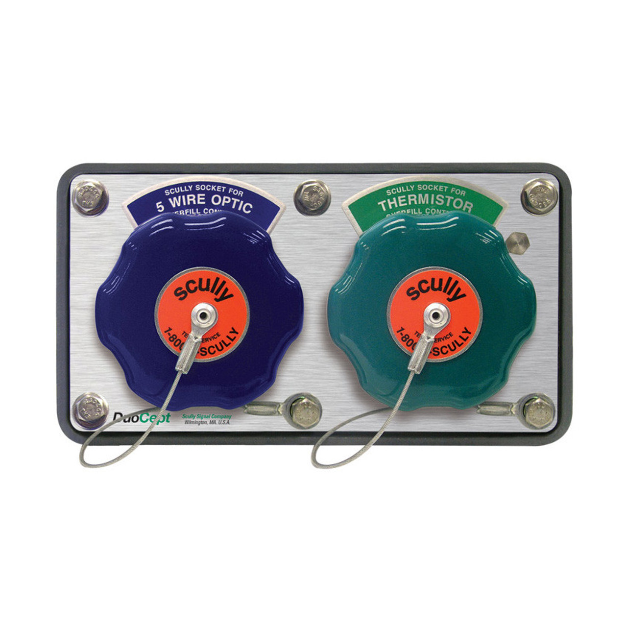
Scully DuoCept™, 5-Wire Optic & Thermistor Overfill Sockets

Support/Resources - Scully Signal
Installation Instructions
TECHNICAL DESCRIPTION

28XX CHECKMATE System with Retain and Overfill | Manualzz
Maintenance & Operating Instructions
Troubleshooting Ground Faults at the Loading Rack

Support/Resources - Scully Signal
0 Response to "37 scully system wiring diagram"
Post a Comment