37 free body diagram pulley system
Jan 13, 2022 · A free body diagram contains only one body, and it shows all the forces acting on that one body. To analyze a situation with more than one body, you draw a separate free body diagram for each body. there is no real apparatus involved -- it's an abstraction; The pulley is a solid disk with a mass of 1.25 kg and an unknown radius. The rope passes over the pulley on the outer edge. What is the acceleration of the blocks? As usual, the first place to start is with a free-body diagram of each block and the pulley.
1. Draw an outlined shape. Imagine the body to be isolated or cut “free” from its constraints and draw its outlined shape. 2. Show all the external forces and couple moments. These typically include: a) applied loads, b) the weight of the body, and c) support reactions (can be difficult). Idealized model Free-body diagram

Free body diagram pulley system
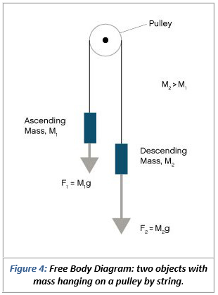
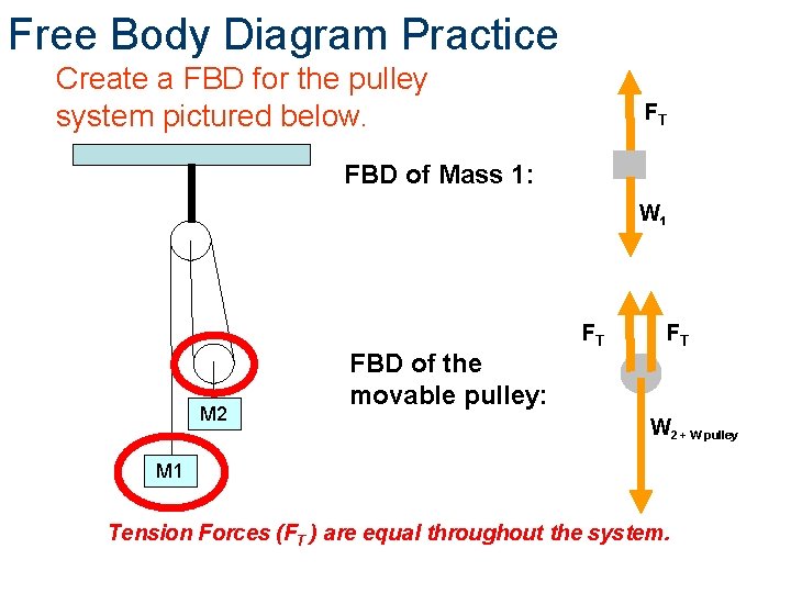
Carefully construct a free-body diagram showing all the forces acting on mass m 2. There are three forces acting on this mass -- the string exerts a force T, the (frictionless) inclined plane exerts a "normal" force n, and gravity pulls down with a force of w 1 = m 1 g. (the pulley is ! assumed massless); string . B. pulls down on the pulley on each side with a force, T, P , ! which has magnitude . T. B. String . A. holds the pulley up with a force . T, P . with the magnitude . T. A. equal to the tension in string . A. The free-body diagram for the forces acting on the moving pulley is shown in Figure 8.41(d). Thus, the coordinate system is chosen for m 2 has the positive y-axis directed downward; the coordinate system chosen for m 1 has the positive x-axis directed rightward. With this selection of axes, the direction of acceleration will be positive for each object. The free-body diagram for each individual mass is shown below.
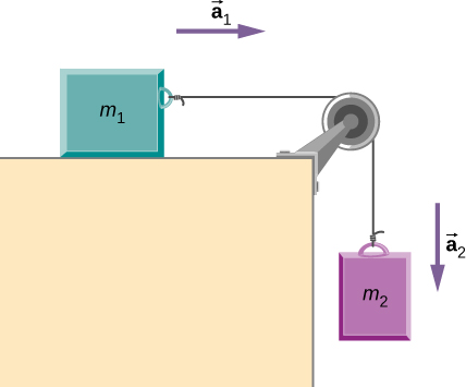
Free body diagram pulley system. Jul 08, 2021 · Pulley problems for IIT JEE and JEE Main - Excellent way to practice free body diagrams and master application of newtons second law of motion. Thus, the coordinate system is chosen for m 2 has the positive y-axis directed downward; the coordinate system chosen for m 1 has the positive x-axis directed rightward. With this selection of axes, the direction of acceleration will be positive for each object. The free-body diagram for each individual mass is shown below. (the pulley is ! assumed massless); string . B. pulls down on the pulley on each side with a force, T, P , ! which has magnitude . T. B. String . A. holds the pulley up with a force . T, P . with the magnitude . T. A. equal to the tension in string . A. The free-body diagram for the forces acting on the moving pulley is shown in Figure 8.41(d). Carefully construct a free-body diagram showing all the forces acting on mass m 2. There are three forces acting on this mass -- the string exerts a force T, the (frictionless) inclined plane exerts a "normal" force n, and gravity pulls down with a force of w 1 = m 1 g.
A mass M is held in place by an applied force F and a pulley ...

Pulley and Cables Free Body Diagram in 2 Minutes! (Example)
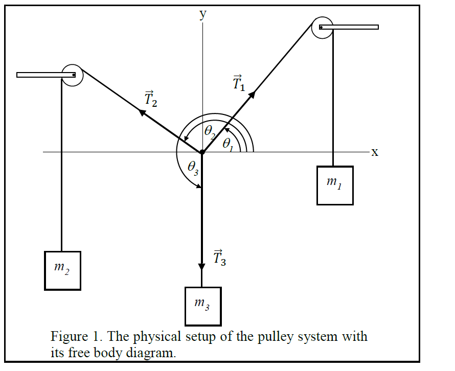
Solved 2 3 Figure 1. The physical setup of the pulley system ...

Free Body Diagrams For any complicated situation, Isolate each object;
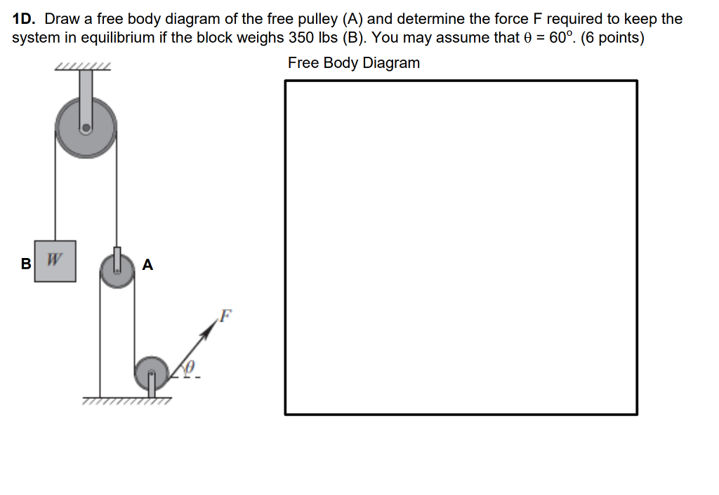
Solved 1D. Draw a free body diagram of the free pulley (A ...
Frames and Machines

Statics eBook: Equilibrium & Free Body Diagrams

Two masses hanging from a pulley (video) | Khan Academy
Pulley system, find the acceleration and tension | Physics Forums
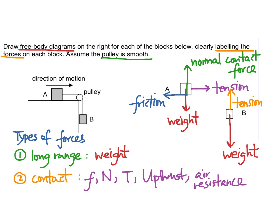
Drawing free body diagrams of boxes linked by strings over a ...
Basic Mechanics
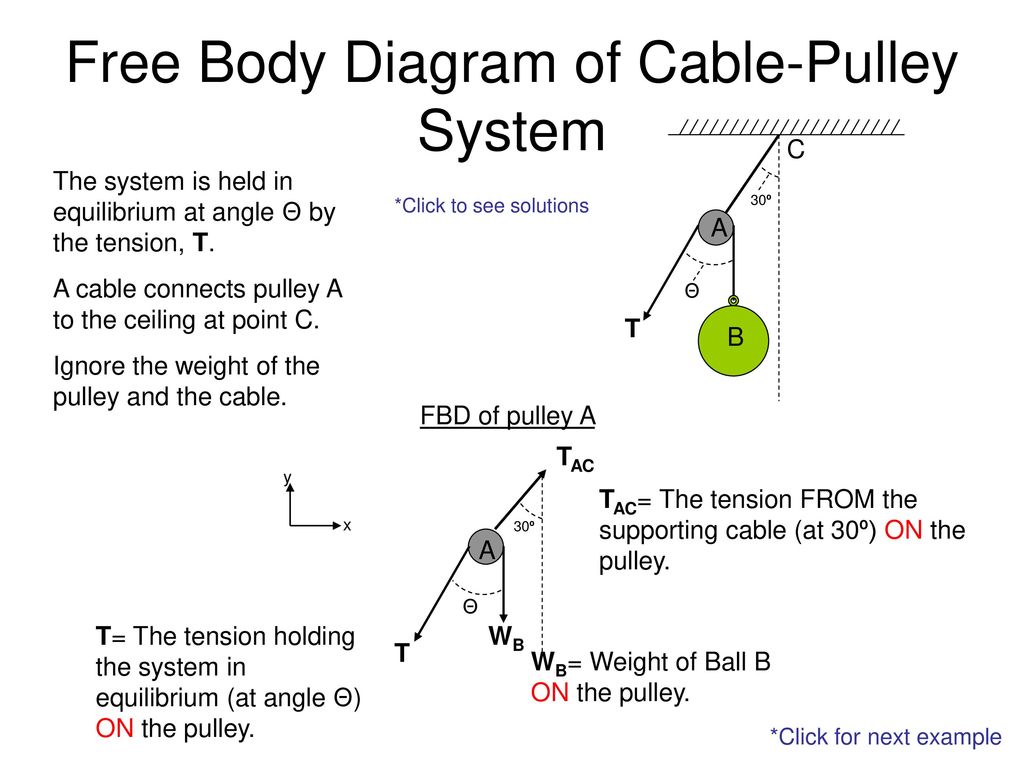
Free Body Diagram of Cable-Pulley System - ppt download

In the system shown below the double pulle... | Clutch Prep

Pulleys - Physics for K-12 - OpenStax CNX
5.7 Drawing Free-Body Diagrams | University Physics Volume 1

The Free Body Diagrams Of The Two Hanging Masses Of - Newtons ...

Find the motion of mass, m, of the mass-pulley system when it ...
Solved Use the free body diagram of the pulley (Figure 4) to ...
even more lifting a pulley system shown in figure p 715 will allow you to lift heavy objects in the

Cable versus Pulley System in Weight Machine by ...

Solved C. Torque and angular acceleration. 1. Draw an | Chegg.com
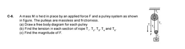
C-6. A mass M is held in place by an applied force F and a ...
solution
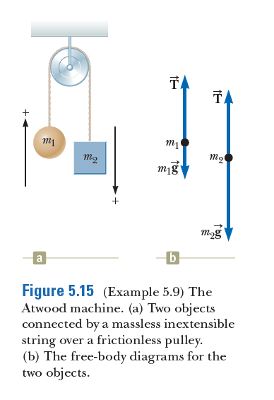
Answered: TA TA + m2 m2 mig mog b Figure 5.15… | bartleby
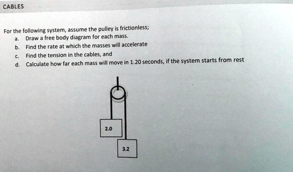
SOLVED:CABLES For the following system, assume the pulley is ...
Free Body Diagrams Principles of Engineering 2012 Project
MCAT Physics Question 21: Answer and Explanation_maintests.com
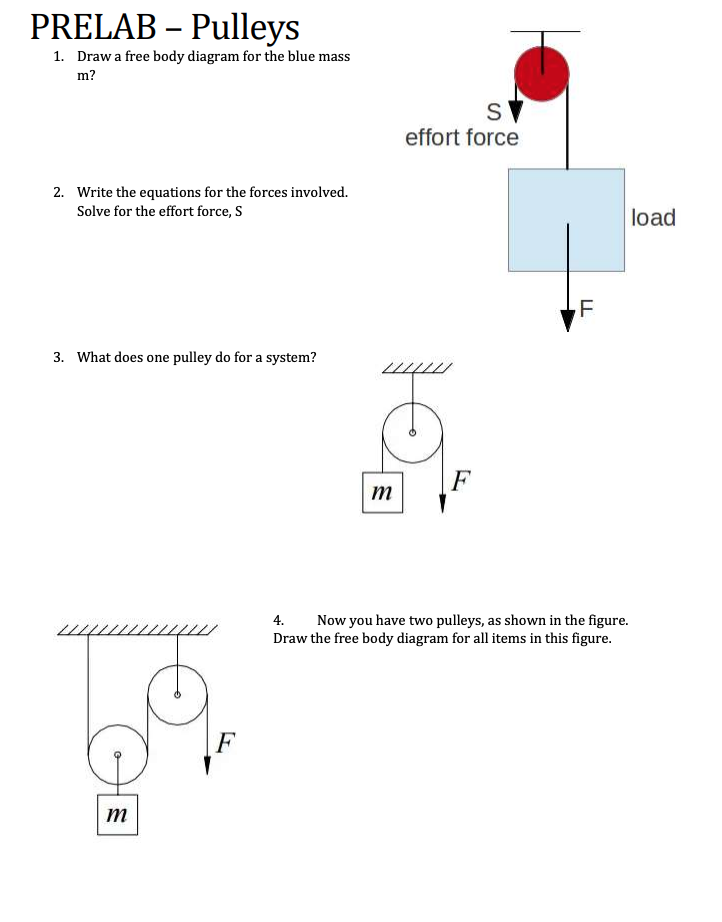
Solved PRELAB – Pulleys 1. Draw a free body diagram for the ...
Two-Body Problems
Two blocks of mass m1 and m2 attached by mass less string are ...
Horizontal pulley

Belt and Pulley Devices, the Simple Answer.
draw free body diagram of two blocks connected with a mass ...

Pulleys - Physics for K-12 - OpenStax CNX

Tips And Tricks to Solve The Mechanics Problems Using Free ...
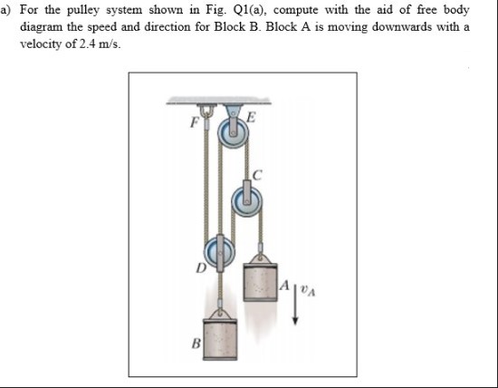
Answered: a) For the pulley system shown in Fig.… | bartleby

Levers and Pulleys in Translating Mechanical Systems
0 Response to "37 free body diagram pulley system"
Post a Comment